This page serves as a list of quick visual references for identifying unknown parts on a printed circuit board (PCB).
Letter Designators
Generally, boards mark component positions with a letter designating what type of part it is, followed by a number to identify that component specifically on that board, e.g. R13 for a resistor.[1]
| Reference Designator | Component |
|---|---|
| A | Sub-assembly |
| C | Capacitor |
| D | Diode |
| F | Fuse |
| FB | Ferrite bead |
| FC | Filter |
| J | Jack connector |
| JP | Jumper |
| K | Relay |
| L | Inductor |
| M | Motor |
| P | Plug |
| PS | Power supply |
| Q | Transistor |
| R | Resistor |
| S or SW | Switch |
| T | Transformer |
| TP | Test point |
| U | Integrated circuit |
| X or Y | Crystal for oscillator |
| Z | Zener diode |
Resistors
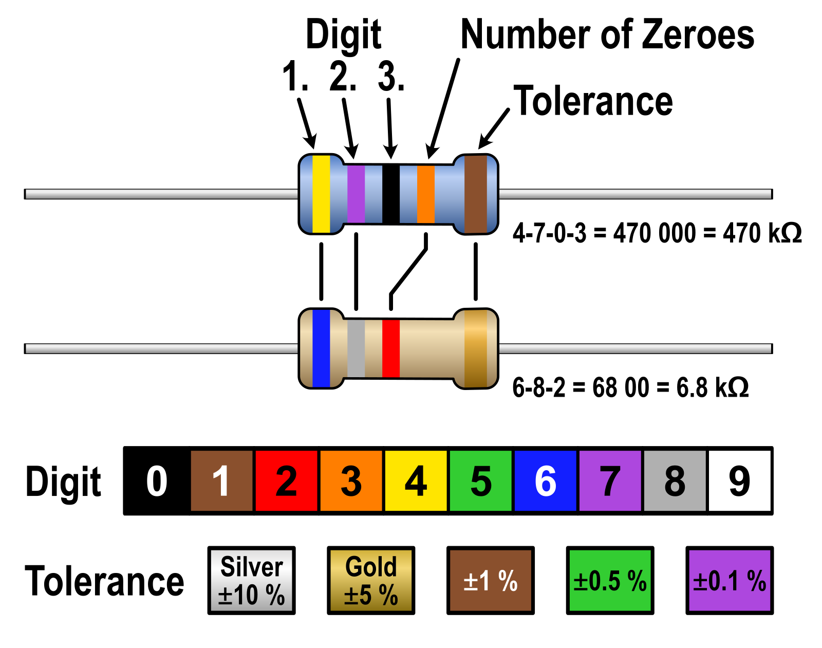
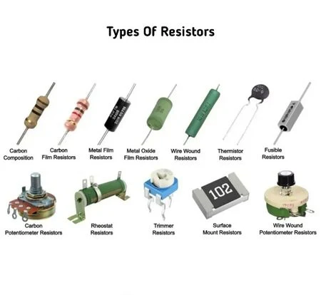
Resistors reduce current in series and reduce voltage in parallel. Resistors have two leads and are not polarized — meaning they can be soldered onto the board in either orientation. If you have an unknown value thru-hole resistor, you look at the color bands (either 4 or 5 bands) on it and use the chart below or this calculator to determine the value.
Capacitors
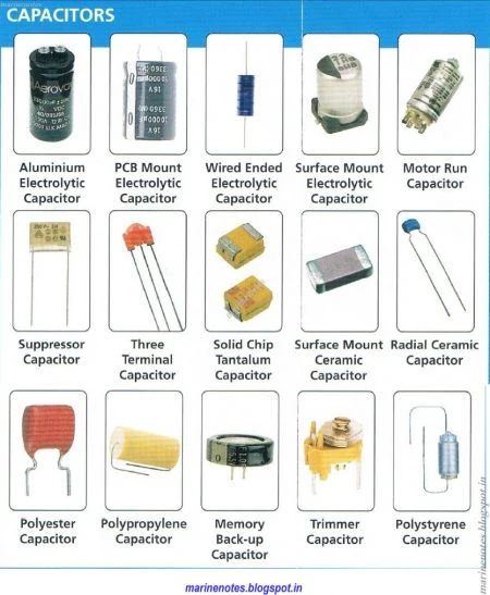
Capacitors temporarily store voltage and smooth out changes in voltage. They can be polarized (positive and negative sides) or non-polarized. Generally, boards mark capacitors with the letter C followed by the number on the board (such as C13) to uniquely identify it on a schematic. Generally, capacitors will list their capacitance (pF, μF, F) and their max voltage rating (V). Capacitors come in a variety of shapes as shown below.
Inductors
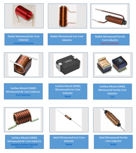
Inductors temporarily store current in the form of a magnetic field and smooth out changes in current. They are generally not polarized — meaning they can be soldered onto the board in either orientation. Inductors come in a variety of shapes as shown below.
Diodes
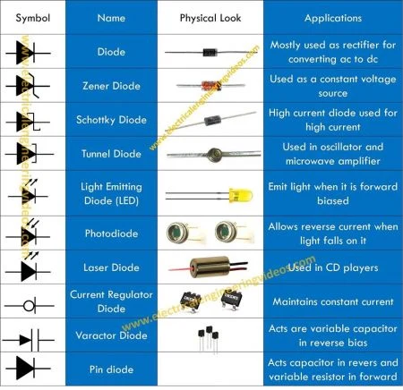
Diodes force electricity to flow in one direction. As such, they are always polarized — meaning they must be soldered in the correct orientation so that current flows in one direction. Diodes come in a variety of shapes as shown below.
IC Package Types
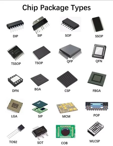
An Integrated Circuit (IC), generally known as chips, are circuits in a compact package. These circuits contain tiny versions of the other components listed here, such as resistors, capacitors, and transistors. Chips are generally made in standard shapes (packages), some of which are shown in this identification chart.