 | Identify a low temperature that your solder consistently melts at by referencing your solder's datasheet to avoid overheating solder pads/vias and increasing risk of ripping pads. |
Electrolytic capacitors are the most common component in need of replacing in older electronics. All electrolytic capacitors have a specified lifespan in their datasheet. Generally, most capacitors start to fail after approximately 20 years as they are prone to leaking or drying out over the span of decades. The capacitor plague also accounts for high failure rates of popular capacitors made between 1999 and 2007. This page is a reference for how to remove old capacitors and install new ones. In some cases, you may wish to replace undamaged capacitors with ones of a different value for specific effects (such as replacing a ceramic filtering capacitor with a different rated one to eliminate noise).
If you did not buy an existing kit of capacitors made for a specific device, you might want to consider building a capacitor kit and sharing it (after verifying functionality).
Information
Capacitor Values
Polymer vs 'wet' capacitors
Polymer capacitors have a solid electrolyte and typically have better service life than non-solid capacitors and do not burn or explode in case of shorts (though they will fail less obviously).[1] The downsides of 'polymer' capacitors are that they're generally more expensive, have a higher leakage current and are damageable by transients and higher voltages spikes.[2] Generally, it is recommended to stick to the original type for stability of the console. But in case you're absolutely worried about motherboard damage (by leaking/burning) or want the highest service life, you may consider polymer capacitors.
Capacitance
The capacitance (uF) should be the same (or really close), for a 3300uF capacitor, you may get away by using 2x 1500uF capacitors in parallel but depending on the location on the board you may need to get creative to connect them both.
Rated voltage
When choosing a capacitor, make sure the rated voltage (V) is the same or more than the original capacitor. The voltage on a capacitor indicates how much volts it can handle, not what it outputs. You can use a 16V capacitor instead of a 10V capacitor, but not the other way around. Technically higher voltage rating is better but maximizing it is not important.
Equivalent series resistance
mOhms refers to impedance. Generally, lower is better, but there's rare exceptions. VRM capacitors must be low impedance similar to the originals.
Ripple current
Ripple current is the fluctuation of current as a component draws/stops drawing power. With rated ripple current, higher is always better.
Capacitor lifetime
A capacitors lifetime is measured in hours at given temperature. Higher temperature ratings are always recommended as the capacitor will last longer at hotter temps.
Well-Known Bad Capacitors
- Xbox Clock Capacitor (causes multiple issues)
- Xbox Nichicon hm capacitors (causes audio/video or power issues)
- All Game Gear and model 1 Sega CDs need a full recap at this point (audio/video issues)
- Sega CDX / Multi-Mega
- TurboDuo / PC Engine Duo capacitors generally corrode nearby components or traces (power, disc loading or audio issues)
- TurboExpress / PC Engine GT and PC Engine LT always need recaps and nearby components can be damaged
- Amiga 600 and 1200 computers require full recaps due to leaky SMD capacitors
- Sega Saturn consoles with the VA0 through 0.8 board revisions
- SNES and Super Famicom consoles with the SHVC-CPU-01 board revision
- Multiple 30+-year-old computer power supplies
- NES AV/power modules (especially the large 2200 μF filter capacitor)
- Fujitsu FM-7 computers also tend to have leaky capacitors on the motherboard
- Many Macintosh computers from the late 1980s to the mid 1990s have leaky surface mount electrolytic capacitors on the motherboard
- GameCube Optical Drive capacitors (causes Disc Read Errors or crashes console)
Highly Recommended for capacitor replacement
Although not mandatory, it is well accepted within the community and recommended at this point to recap the following:
- Xbox PSU (mainly the Teapo capacitors on Foxlink versions) & 25v 100μF capacitor at C3B2 (can cause video issues)
- 1.0/1.1 Foxlink PSU also infamously has bad solder joints for the AC input, causing it to be a literal fire hazard. It's recommended to replace the original solder for the AC connector with fresh leaded solder.
- Xbox 1500μF and 3300μF motherboard capacitors (including Chemi-Con branded ones)
- PS2 PSU (fat models)
- PS1 PSU and the 220 μF capacitors filtering the luma and composite video signals
- Dreamcast PSU
- Saturn PSU
- PAL 3DO FZ-1 units
- PAL SNES
- Early revision (VA0-VA4) Sega Genesis and Mega Drive consoles, especially those manufactured in Taiwan
- FMT Marty PSU and audio filtering capacitor
- N64 PSU
- Any PCE CD hardware
- A/V Filtering Caps on the Wii (causes dark or no video output)
Sourcing Capacitors
Any capacitor may (temporarily) work, but in case you're looking to extend the lifetime of your console significantly, it may be worth to purchase capacitors from a commonly known brand. You should only purchase capacitors from known parts stores to avoid counterfeits, such as:
- Console5
- DigiKey
- Mouser
- Farnell (UK)
- RS-Online (UK)
A sample of trusted brands of capacitors commonly used in capacitor replacements are:
- AVX
- Chemi-con
- KEMET
- Nichicon
- Panasonic
- Rubycon
- Vishay
- Würth
Any big electronics brand such as 'Samsung', 'Hitachi' or 'TDK' should be fine as well.
Replacement Process
Identifying Bad Capacitors
As mentioned before, all electrolytic capacitors have a stated lifespan and will fail eventually. Often times — but not always — when capacitors fail, it is visibly apparent. The top of the capacitor bulges instead of being flat or it burst and leaked. The most problematic situation is if the capacitor leaks liquid electrolyte underneath itself onto the circuit board, which can cause shorts, corrode pins on chips, or — depending on the composition of the fluid — it can eat through the circuit board and damage traces. Due to its liquid nature, the fluid can also flow through holes in the board or vias and affect components on the other side of the board and the vias themselves.
However, capacitors can silently fail without any visible signs. In order to fully test them, you will need to remove the capacitor from the board and measure it with a capacitor tester. With the low cost of capacitors, it is often a better idea to just replace the capacitor if it's suspected to be failed.
Methods
- Measuring the capacitance out of circuit: An electrolytic capacitor should be replaced if its capacitance (in farads) is ±20% outside of its rated value. Using a capacitance meter, measure the capacitor and check its value. It's best to do this out of circuit by removing the capacitor from the board and testing it on its own, but this may not always be possible (e.g., with surface-mounted electrolytics). Testing in-circuit is possible, but other components on the board will skew the readings.
- Measuring the capacitor's ESR: Electrolytic capacitors have an equivalent series resistance (ESR) which is only measurable at certain frequencies with a dedicated meter. When a capacitor fails, its ESR will increase, often well beyond its rated value. Plenty of tables with worst-case ESR values are available on the Internet, and in some cases are printed on the ESR meters themselves.
- Continuity test: Set your multimeter to continuity/diode test and measure the capacitor. The meter should beep (show continuity) only for about a second, and the display should show a value gradually creeping upwards from 0 as the capacitor charges. If it beeps constantly, the capacitor has failed shorted. If it doesn't beep at all, it's open circuit. This test works best on larger value electrolytics or for detecting shorted caps (multi-layer ceramics being the worst offenders).
Capacitor Removal
The method you use to remove capacitors depends on the type of capacitor and how it is installed. Note that there are products such as Chip Quik solder paste which reduces the melting point of the solder on board, thus keeping solder liquid for a longer period of time, allowing for easier removal of capacitors.
Through-Hole Electrolytic Capacitors
- If the through-hole capacitor is not flush to the board and you can see the legs underneath:
- Use flush cutters to snip each leg to remove the can. From there, you can remove each leg by holding it with tweezers then heating the solder hole and lifting the leg out. Ensure that you wait until the solder is completely liquid before lifting the leg out to avoid accidentally pulling metal out with it.
- If the through-hole capacitor sits flush to the board:
- Position the board in a way that you can access both the top and bottom of the board. Heat one solder hole completely and gently lean the capacitor to lift the leg a small bit. Repeat the process, alternating legs until it is completely removed.
Electrolytic Surface Mount Capacitors
Surface mount capacitor removal runs a higher risk of ripping a solder pad off of the motherboard. They consist of the radial can, a plastic base that the can sits on, and leads that go through the plastic base and connect to the surface of the motherboard.
| Identify a low temperature that your solder consistently melts at by referencing your solder's datasheet to avoid overheating solder pads/vias and increasing risk of ripping pads. |
| While some recommend heating and lifting one side at a time, this is NOT recommended as it has a high risk of ripping a pad off of the board. See the troubleshooting section if a pad is ripped. |
There are two popular methods to remove these capacitors:
- Heating each lead of the capacitor until the solder is liquified and lift the capacitor off of the board. You will likely need to use Chip Quik or soldering tweezers to be able to keep both leads liquified simultaneously. This runs the risk of solder solidifying before lifting the board, resulting in a pad being ripped off the board. Generally, you would not apply any force in the lifting action, but often times if a capacitor has leaked, the capacitor will be stuck on the board due to the fluid dying underneath.
- The "push and twist" method is a controversial method. This involves using pliers to grab the capacitor can, pushing gently downwards, and rotating the capacitor in a complete circle until the leads break off against the plastic base. From there, you can snip any remnants of leads above the plastic base, and the base will lift away using zero force. The very bottom of the leads will still be attached to the motherboard and will require you to heat and lift them away with tweezers. This is controversial because of the high risk of damaging the solder pads underneath the capacitor. However, in some cases, the leaked electrolytic fluid will have weakened the solder joints to the point where the capacitor will come off with very little pressure.
Ceramic Surface Mount Capacitors
Generally, there are two methods to removing ceramic surface mount capacitors:
- With a soldering iron. Either use Chip Quik to heat liquify both pads and knock the capacitor away with the iron or lift it away with tweezers. Alternatively, you can add a bunch of solder to one side and blob the solder over to the other pad, effectively liquifying both sides at the same time so that the capacitor can be removed.
- With hot air. See the Replacing ICs page for tips on hot air rework.
Cleaning the Area
If a capacitor has leaked, generally it will look like a very faint dark stain on the board. If it was wicked up by dust, it may look different in appearance to dust in other areas on the board. To clean this, liberally wipe the area using a cotton swab and 90% or higher isopropyl alcohol or vinegar. Visibly inspect to make sure that nearby components — and components on the other side of the board if there are open holes or vias in the board that it could have flowed through — are not damaged.
Capacitor Installation
Ensure that you have cleaned the area thoroughly before installing new capacitors. Ensure that the pads or holes that you are attaching the new capacitors to are clean looking and have an appropriate amount of solder on them.
Through-Hole Electrolytic Capacitors
- If the leads of the capacitor are not straight, gently bend them to be straight.
- Check the orientation of the positive and negative holes on the board and insert the capacitor aligning the negative hole with the negative lead, and the positive hole with the positive lead.
- If the capacitor will not insert all the way flush to the board, remove it and use tweezers to bend the leg once or twice to get it to fit and sit nearly flush. Avoid bending the leads up inside the can.
- With the capacitor inserted, heat the solder hole and lead at the same time on the opposite side, and add solder to it. Repeat for the other lead.
- Trim the leads so that they do not short on anything else. If possible hold or shield the leads with your hand so that there's no possibility of it being shot into your eyes.
Electrolytic Surface Mount Capacitors
- If you have solder paste, add some to the solder pad.
- Check the orientation of the positive and negative holes on the board and place the capacitor on the board, aligning the negative pad with the negative lead, and the positive pad with the positive lead.
- Holding the capacitor in place with one finger, touch your tinned soldering iron to the lead and the pad at the same time to make the connection.
Ceramic Surface Mount Capacitors
Ceramic surface mount capacitors are non-polarized, meaning that they can be installed in either orientation. Simply hold the capacitor in place with tweezers, solder one side and wait for it to cool before letting go of the capacitor and soldering the other side. Using flux is highly recommend as it will help the solder flow to the pads.
Troubleshooting
If you ripped a solder pad off of the board. Check if it is still connected to the trace on one side.
- If it is, you can put a very tiny drop of super glue underneath the pad and glue it down in place.
- If it is not connected to the trace, visually follow the trace to the nearest pad, connected component, or via and solder a wire between that point and the lead of the capacitor.
Wall of Shame, or Why Replacing Capacitors is So Important
-
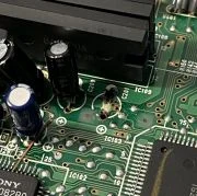 The through-hole capacitors on this PC Engine Super CD-ROM2 appeared to be in good condition, but appearances can be deceiving, as this particular capacitor and its neighbor (C200) had actually leaked.
 -
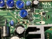 More leakage was found on C311 nearby.
 -
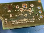 Three capacitors on the sub board of this Japanese Mega CD had leaked to the point where the fluid seeped through to the other side and corroded much of the solder joints shown here. Some trace repair was required in order for the system to even power on.
 -
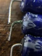 This capacitor was pulled from a Fujitsu FM-7 computer and shows extensive corrosion on the lead from leakage. Fortunately the motherboard suffered no damage and functioned normally after a recap.
 -
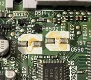 Both capacitors C550 and C551 on this PSone console had leaked, causing the luma and composite video signals to become weak and unstable. Fortunately no board damage resulted, and the console functioned normally after a cleaning and capacitor replacement.
-
 NES that needs a recap. Note the wavy lines in the output, which is common when using the original 9V AC power supply, and the capacitors need replacing.
 -
 Same NES, but this time with a cheap 9V DC switching power supply. Instead of wavy lines, we see jailbars instead.
 -
 Same NES after all capacitors have been replaced. Much better!