Cartridge Port
This connector has 44 pins and has a pin pitch of 3.18 mm.
Note: Pins A1 through A22 are towards the back and numbered from left to right, B1 through B22 are towards the front and also numbered from left to right. On the SC-3000, A1 through A22 are towards the bottom and B1 through B22 are towards the top.
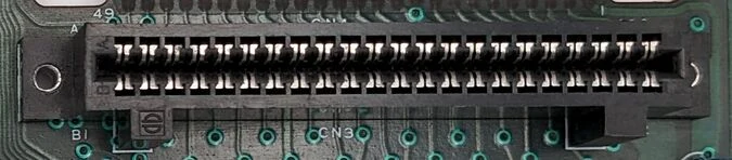
| Pin # | Description | Pin # | SG-1000 | SG-1000 II | SC-3000 | |
|---|---|---|---|---|---|---|
| A1 | A0 | B1 | VCC | |||
| A2 | A1 | B2 | VCC | |||
| A3 | A2 | B3 | OSRAM | CSRAM | OSRAM | |
| A4 | A3 | B4 | EXM1 | CEROM | ||
| A5 | A4 | B5 | RD | MEMR | ||
| A6 | A5 | B6 | WR | MEMW | ||
| A7 | A6 | B7 | Unused | I/O R | ||
| A8 | A7 | B8 | Unused | I/O W | ||
| A9 | A8 | B9 | RFSH | Unused | ||
| A10 | A9 | B10 | MREQ | |||
| A11 | A10 | B11 | CONT | |||
| A12 | A11 | B12 | Unused | RAS1 | ||
| A13 | A12 | B13 | Unused | CAS1 | ||
| A14 | A13 | B14 | Unused | RAM A7 | ||
| A15 | D0 | B15 | Unused | RAS2 | ||
| A16 | D1 | B16 | Unused | CAS2 | ||
| A17 | D2 | B17 | Unused | MUX | ||
| A18 | D3 | B18 | A14 | |||
| A19 | D4 | B19 | EXM2 | A15 | ||
| A20 | D5 | B20 | M1 | Unused | ||
| A21 | D6 | B21 | GND | |||
| A22 | D7 | B22 | GND | |||
Controller Port
Note: Female is connector at the console. Male is connector at the controller. Diagram pictured is of the connector at the controller end. This pinout is mostly identical to the later Sega Master System and Mark III.
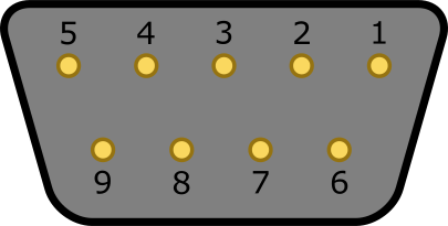
| Pin # | Description |
|---|---|
| 1 | Up |
| 2 | Down |
| 3 | Left |
| 4 | Right |
| 5 | Unused (SG-1000 and SC-3000) VCC (SG-1000 II) |
| 6 | Button 1 |
| 7 | GND (console side only on SG-1000 and SG-1000 II) Unused (SC-3000 only) |
| 8 | GND (SG-1000 and SG-1000 II) Pin 7 of 74LS145 (SC-3000) |
| 9 | Button 2 |
Expansion Port
This expansion port is only found on the SG-1000, SG-1000 II and Othello Multivision FG-2000 consoles.
Note: Numbering runs from 1 to 25, with the mechanical key at position 17 (24 electrical contacts). With the component side of the board facing you and the expansion connector edge nearest you, numbering runs right to left on the SG-1000 and left to right on the SG-1000 II. These directions reverse when viewed from the solder side. Pins 1 and 2 are +5 V; pins 22–25 are GND. The compatible 50-contact cable connector accommodates contacts on both sides of the board edge.
| Pin # | Description | Pin # | Description |
|---|---|---|---|
| 1 | +5 V | 14 | KBSEL |
| 2 | +5 V | 15 | RD |
| 3 | JOYSEL | 16 | WR |
| 4 | A0 | 17 | Mechanical key (no electrical contact) |
| 5 | A1 | 18 | CONT |
| 6 | D0 | 19 | Unused (SG-1000) / IORQ
(SG-1000 II) |
| 7 | D1 | 20 | Unused |
| 8 | D2 | 21 | Unused (SG-1000) / A2 (SG-1000 II) |
| 9 | D3 | 22 | GND |
| 10 | D4 | 23 | GND |
| 11 | D5 | 24 | GND |
| 12 | D6 | 25 | GND |
| 13 | D7 |
Printer Port
This connector is only found on the SC-3000 and SK-1100 keyboard. Note: Female connector is pictured.
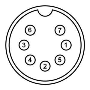
| Pin # | Description |
|---|---|
| 1 | FAULT |
| 2 | BUSY |
| 3 | DATA |
| 4 | FEED |
| 5 | RESET |
| 6 | Unused |
| 7 | GND |
SC-3000 Monitor Out
Note: Female connector is pictured. The same pinout is also used on the Master System and Genesis/Mega Drive.
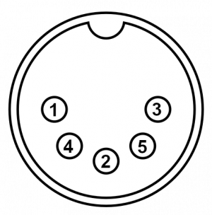
| Pin # | Description |
|---|---|
| 1 | Composite Video Out |
| 2 | GND |
| 3 | Audio Out |
| 4 | Unused |
| 5 | Unused |
Yeno SC-3000 Monitor Out
Note: Female connector is pictured.
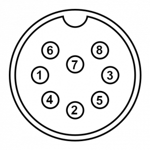
| Pin # | Description |
|---|---|
| 1 | Composite Sync |
| 2 | GND |
| 3 | Audio Out |
| 4 | Vertical Sync |
| 5 | Horizontal Sync |
| 6 | Green |
| 7 | Blue |
| 8 | Red |