Cartridge Port
Note: Pins 1 through 12 are at the front and numbered from left to right. Pins 13 through 24 are at the back and numbered from right to left.
| Pin # | Description |
|---|---|
| 1 | A7 |
| 2 | A6 |
| 3 | A5 |
| 4 | A4 |
| 5 | A3 |
| 6 | A2 |
| 7 | A1 |
| 8 | A0 |
| 9 | D1 |
| 10 | D2 |
| 11 | D3 |
| 12 | Ground |
| 13 | D4 |
| 14 | D5 |
| 15 | D6 |
| 16 | D7 |
| 17 | D8 |
| 18 | A12 |
| 19 | A10 |
| 20 | A11 |
| 21 | A9 |
| 22 | A8 |
| 23 | 5V |
| 24 | Ground |
Controller Port
Note: Female is connector at the console. Male is connector at the controller. Diagram pictured is of the connector at the controller end.
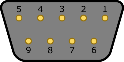
| Pin # | Description |
|---|---|
| 1 | Up |
| 2 | Down |
| 3 | Left/Left Paddle Button |
| 4 | Right/Right Paddle Button |
| 5 | Right Paddle Potentiometer |
| 6 | Fire Button |
| 7 | 5V |
| 8 | Ground |
| 9 | Left Paddle Potentiometer |