Early revisions of the model 2 Genesis/Mega Drive, specifically the VA0, VA1 and VA1.8 boards, are known for their lower quality audio compared to most model 1s and even the later VA3 and VA4 model 2s. However, it is possible to improve the audio on these systems without resorting to a more invasive mod such as a Triple Bypass or Mega Amp. This can be done by swapping a few component values on four capacitors and resistors in the input stage, as well as swapping both op-amp chips. Additionally, a few passive components must be added as necessary. You can also perform a similar mod with VA7 model 1 units, as there are some similarities.
Overview
A significant cause of the reduction in audio quality for these consoles is the choice of op-amp chips used in the audio circuit. In all of these consoles, Sega used variations of the LM324 quad op-amp, an extremely common and inexpensive part. However, they have low dynamic performance and high crossover distortion, making them less than ideal for audio.
Additionally, the VA0 through 1.8 Model 2, as well as the VA7 Model 1, use a particularly strong Sallen-Key low-pass filter with a too-high Q-factor on the FM channels, greatly reducing the frequency response and causing short-lived 'ringing' oscillations on some high-frequency sounds. In addition, the resistors chosen were inadequate in value, resulting in additional distortion as the signal overloads the op-amp's inputs (which on +5V single supply are rather limited in common-mode range). By changing these passive components, you’ll be fixing not only distortion, but the wonky Q-factor as well.
Note for Model 1 VA7, though the audio will be excellent, there is the problem with the headphone amp which will distort after volume reaching over 8 and higher. It's due to the inadequate voltage swing and unfortunately will require rewiring the circuit. It’s best to replace that headphone circuit.
Materials and Tools Needed
- JIS or Phillips head screwdriver
- Soldering iron
- Hot air soldering station or ChipQuik
- Leaded solder
- Flux
- Desoldering braid
- Tweezers
- Kapton tape
- Two SOIC-14 package, quad op-amp chips of higher performance than the '324 type amps (it is recommended to purchase these from reputable distributors such as Digi-Key or Mouser, as AliExpress and eBay may contain fakes). Most general-purpose op-amps of sufficient performance at +5V single supply (this translates to -/+ 2.5V minimum operating voltage when reading most datasheets) should work. Recommended chips:
- TL974I (relatively cheap and works great)
- MC34074 (direct functional upgrades to LM324, fixes their crossover distortion and dynamic performance)
- OPA4171 (expensive)
- OPA4991 (expensive, direct functional upgrade to OPA4171)
- MC33204 (high output current, fully rail-to-rail)
- TS924 (80mA output drive, rail-to-rail)
- TLV9104 (relatively new part, rail-to-rail)
- Avoid amplifiers with known output phase reversal problems, such as the TL074, as one of the op-amps is used for the reset circuit.
- Four 27 pF (58 kHz) 0805 SMD capacitors for the Sallen-Key FM filter
- Four 100k ohm 0805 SMD resistors
- Two 56 pF (60 kHz) 0805 SMD capacitors (Model 2 only)
- Two 75 ohm resistors (Model 2 only)
- Six 10k ohm 0805 SMD resistors (Model 2 only)
- Two 4700 pF 0805 SMD capacitors (Optional if you prefer VA2 Model 1's 3.38 kHz filter knee)
- Two 10uF 25V 0805, X5R/X7R SMD capacitors
Procedure (VA7 Model 1)
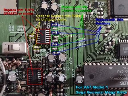
The VA7 Model 1 requires a somewhat different procedure due to how different the audio hardware after the FM low pass filter is.
- Unscrew the six screws on the bottom case. Carefully pull off the top case and remove the connector on the power LED itself. You may need to straighten out the LED leads with a pair of needlenose pliers as they are typically bent over. Do not remove the power LED on the motherboard end as the connector is soldered directly to the board.
- Undo the screws securing the RF shielding, including the two securing the cartridge port. Remove the motherboard and set the bottom case aside. Locate the audio circuitry, which is to the right of the power switch.
- Add flux on capacitors C53, C54, C55 and C56, as well as R74, R75, R76 and R77, then add a small blob of solder onto your iron. Place your iron tip on both ends of each capacitor and carefully "sweep" them off the board.
- Use desoldering braid to clean up the remaining pads. Make sure to use additional flux as needed so you do not burn up and lift the pads.
- For C53, C54, C55 and C56, place 27 pF capacitors on the pads using tweezers. Apply flux and solder in place.
- For R74, R75, R76 and R77, place a 100k ohm resistor on the pads as before. Apply flux and solder in place.
- You can adjust the output filter knee to your liking by changing the capacitors at C19 and C20. 1800pF gives 3.27 Khz, whilst 2000pF gives 2.94 kHz.
- If you want something else, you can use a lowpass filter calculator tool like this one to figure out what value of capacitors you need. For example, 390 pF will give a 15.1 kHz filter knee with the stock 27K gain resistors, which is pretty close to the 'unfiltered' audio option of the Mega Amp.
- Replace the LM324-type op-amp chips with better op-amps.
- For removal with hot air, place Kapton tape or tin foil on the components surrounding the op-amps so they will not be damaged or accidentally removed by hot air.
- Set your hot air station for low to medium airflow and set the temperature for around 335 degrees Celsius. Hold the nozzle within an inch of the chip and swirl it around so that the heat is applied evenly. After about 10-15 seconds, the op-amp should become loose. Do not force it or make any fast movements as you could damage or lift pads. Repeat this for the other op-amp chip.
- Clean the pads by applying flux and then carefully and lightly dragging desoldering braid over them. Once the old solder has been removed, clean off the area with IPA or flux remover.
- Align the replacement op-amp chip onto the pads by using a strip of Kapton tape to hold it in place. Tack down one leg with solder and flux, then repeat for the opposite corner.
- If the alignment is good, apply a generous amount of flux to the area and then put a small amount of solder on the tip of your iron. Drag the tip across the pads so that the solder flows evenly; the flux will do most of the work for you. If you wind up with a solder bridge, apply more flux and "sweep" the excess solder away onto your iron tip.
- Replace the 0.022uF decoupling caps at C21 and C23 with 10uF MLCC capacitors rated for at least 16V; the higher voltage rating is necessary due to ceramic capacitor derating characteristics. This will help avoid degrading noise performance with higher slew rate op-amps.
- Double check your work and test the console to ensure the sound continues to function properly. If so, enjoy improved audio from your VA7!
Procedure (VA0/1/1.8 Model 2)
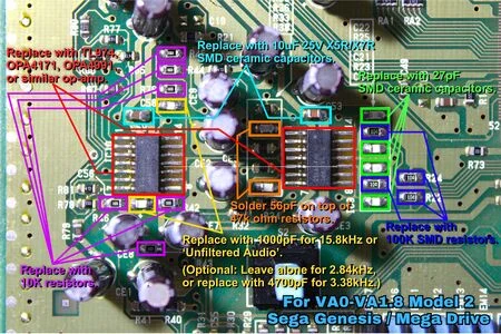
- Flip the console over and unscrew the four JIS/Phillips head screws, then remove the top case.
- Undo the screws securing the RF shielding, including the two securing the cartridge port. Remove the motherboard and set the bottom case aside. Locate the audio circuitry, which is directly above the power switch.
- Add flux on capacitors C20, C21, C22 and C23, as well as R22, R23, R24 and R25, then add a small blob of solder onto your iron. Place your iron tip on both ends of each capacitor and carefully "sweep" them off the board.
- Use desoldering braid to clean up the remaining pads. Make sure to use additional flux as needed so you do not burn up and lift the pads.
- For C20, C21, C22 and C23, place 27 pF capacitors on the pads using tweezers. Apply flux and solder in place.
- For R22, R23, R24 and R25, place a 100k ohm resistor on the pads as before. Apply flux and solder in place.
- For R38 and R39, carefully solder 56 pF capacitors on top of the two 47k ohm resistors using tweezers. Apply flux and solder in place.
- On the underside of the board, solder two 75 ohm resistors from CE1 and CE4 negative lead to Ground.
- For extra caution, add Kapton tape under the two resistors and heat shrinks to the resistor leads to potentially avoid shorting the board, as one of them (resistor connected to CE4 negative lead to ground) is located on top of a 5V plane.
- Remove R42, R43, R44, R45, R46 and R76 using the same method as in steps 3 and 6, and place the 10k ohm resistors on each of the pads. Apply flux and solder in place.
- With the stock output filter capacitors in place you will have a VA3 Model 1-like, 2.84 kHz output filter knee. If you prefer a more VA2-like 3.38 kHz filter knee, then replace C56 and C58 with 4700 pF capacitors.
- If you want something else, you can use a lowpass filter calculator tool like this one to figure out what value of capacitors you need. For example, 1000 pF will give a 15.8 kHz filter knee with the 10K gain resistors you installed, which is pretty close to the 'unfiltered' audio option of the Mega Amp.
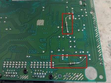
The underside of the Model 2, with 75 ohm resistors already in place.
- If you want something else, you can use a lowpass filter calculator tool like this one to figure out what value of capacitors you need. For example, 1000 pF will give a 15.8 kHz filter knee with the 10K gain resistors you installed, which is pretty close to the 'unfiltered' audio option of the Mega Amp.
- Replace the LM324-type op-amp chips with better op-amps.
- For removal with hot air, place Kapton tape or tin foil on the components surrounding the op-amps so they will not be damaged or accidentally removed by hot air.
- Set your hot air station for low to medium airflow and set the temperature for around 335 degrees Celsius. Hold the nozzle within an inch of the chip and swirl it around so that the heat is applied evenly. After about 10-15 seconds, the op-amp should become loose. Do not force it or make any fast movements as you could damage or lift pads. Repeat this for the other op-amp chip.
- Clean the pads by applying flux and then carefully and lightly dragging desoldering braid over them. Once the old solder has been removed, clean off the area with IPA or flux remover.
- Align the replacement op-amp chip onto the pads by using a strip of Kapton tape to hold it in place. Tack down one leg with solder and flux, then repeat for the opposite corner.
- If the alignment is good, apply a generous amount of flux to the area and then put a small amount of solder on the tip of your iron. Drag the tip across the pads so that the solder flows evenly; the flux will do most of the work for you. If you wind up with a solder bridge, apply more flux and "sweep" the excess solder away onto your iron tip.
- Replace the 0.022uF decoupling caps at C53 and C59 with 10uF MLCC capacitors rated for at least 16V; the higher voltage rating is necessary due to ceramic capacitor derating characteristics. This will help avoid degrading noise performance with higher slew rate op-amps.
- Double check your work and test the console to ensure the sound continues to function properly. If so, enjoy improved audio from your Model 2!
Samples
All samples were recorded using a VA1 model 2 Genesis playing the track "Flood of Power" from Midnight Resistance. Note that these samples were done using the old method of the mod.
- https://consolemods.org/wiki/File:Gen2va1stock.WAV - Audio output from an unmodified console, which is muffled, distorted and noisy.
- https://consolemods.org/wiki/File:Gen2va1capreplacement.WAV - Audio output after replacing C20 through C23. The clarity is considerably improved but some distortion and noise still remains.
- https://consolemods.org/wiki/File:Gen2va1opampreplacement.WAV - Swapping the op-amps with a pair of OPA4171s massively improves the audio quality, with practically all distortion eliminated.
These samples were recorded using a VA7 model 1 Genesis playing "Attack of the Barbarian" from Streets of Rage. Using the new method of the mod, with 56 pF and 120 pF filtering caps in their respective places.
- https://consolemods.org/wiki/File:SOR1AttackoftheBarbabrianStock.wav - Audio output from an unmodified console.
- https://consolemods.org/wiki/File:SOR1AttackoftheBarbabrianOldMod.wav - Audio output from the original Audio Circuit Mod method. Considerably better, But audio is still distorted and clipping.
- https://consolemods.org/wiki/File:SOR1AttackoftheBarbabrianNewModMethod.wav - Audio output from the new and improved method of the Audio Circuit Mod, Now all distortion is pretty much eliminated.
The following video was recorded on a VA1 model 2 Genesis by YouTube user Erik Riker, which shows even more examples. Note that YouTube videos have some audio compression: