Early model 1 Japanese Mega Drives and the earliest US Genesis consoles have slightly overdriven audio from the headphone jack, slightly spoiling what is otherwise well-balanced and clean stereo audio output. Although this issue was corrected with the later VA3 motherboard revision, it can also be corrected on VA0 through VA2 model 1s by substituting several component values. This modification was originally developed by Ace on the Sega-16 Forums.[1] It is also worth noting that this is the only audio modification approved by the 16-bit Audiophile Project for recording high-quality Genesis/Mega Drive game soundtracks.
Note that performing this mod will greatly reduce the volume of the mono output from the AV out and RF. However, through more heavy modification you can restore mono sound to its original volume levels.
Required Materials and Tools
- JIS/Phillips head screwdriver
- Soldering iron
- Leaded solder
- Flux
- Tweezers
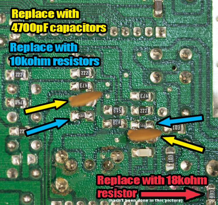
- Two 10K ohm 1206 SMD resistors
- One 18K ohm 1206 SMD resistor
- Two 4700 pF 1206 SMD capacitors
- One 33K ohm SMD resistor
- Some 28 AWG wire
- One TL972 Op Amp or similar (Optional!)
Procedure 1: preamp fix
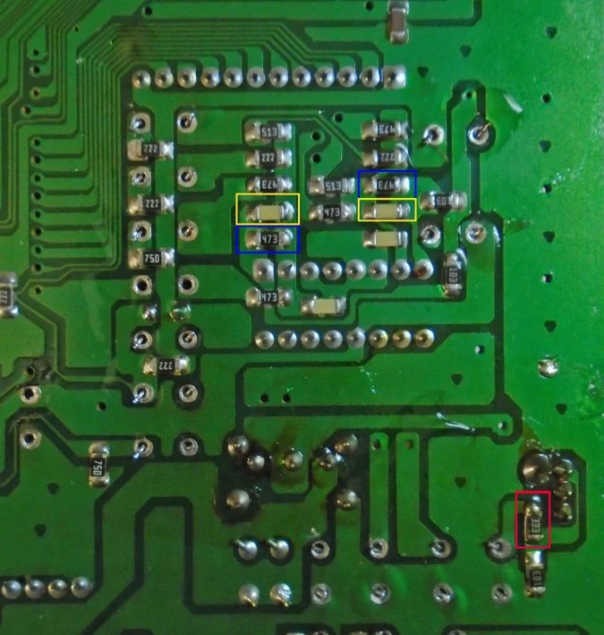
Follow the below picture for whichever motherboard you have.
VA0, VA1 and Japanese VA2
A VA1 is depicted but the points are the same for the VA0 and Japanese VA2.
US VA2
Procedure 2: mono fix (Optional)
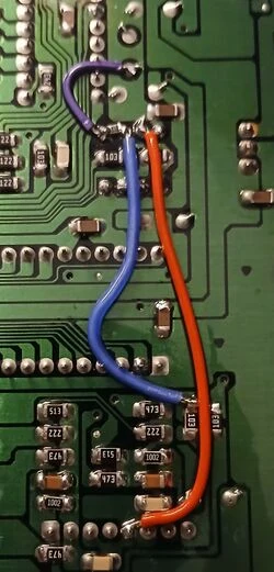
If you wish to bring back the mono audio output's volume levels, then follow these steps
US VA2
- Remove the 8-pin, LM358 op amp from the motherboard. This is located between the Yamaha YM2612 and Sony CXA1145 video encoder
- Cut the traces connecting pins 1 and 2 of the op amp to the negative leg of capacitor C30, then cut the trace joining pins 1 and 2. Test with a multimeter to ensure conductivity is lost.
- Cut the trace going from pin 3 on the topside of the motherboard. If you wish to keep all wiring on the topside of the board, sever down the middle as to allow for step 4
- Connect pin 1 on the motherboard to the negative leg of capacitor C30, then connect the trace originally going to pin 3 of the op amp to pin 2 instead. This can be done from the top or bottom sides of the motherboard.
- After reinstalling the original op amp, or a socket in its place, solder a 33K ohm resistor between pins 1 and 2 of the op amp (Optional!: at this point you may choose to keep the original op amp, or replace it with a more modern amp such as a TL972. If undecided, you may also install a socket to make future upgrades easier).
- Solder a wire from pin 3 of the op amp to pin 5 of the Sony A1034 headphone amp.
- hook up the system to test, and enjoy!
Samples
- https://consolemods.org/wiki/File:Sor2va2.wav - This sample, recorded from a VA2 Genesis, demonstrates what a stock VA0 through VA2 sounds like through the headphone output.
- https://consolemods.org/wiki/File:Sor2moddedva0.wav - How it sounds after the preamp fix. This was recorded from a VA0 Japanese Mega Drive.