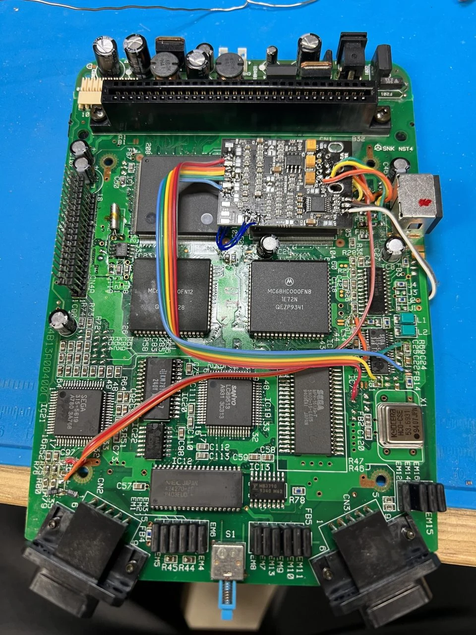
This document will serve as clear step-by-step instructions for installing the 3BP on the Sega CDX.
Jumper SettingsSolder the “2” jumpers.
If removing the solder 2.2K resistor for PSG as detailed below, solder the d-right jumper.
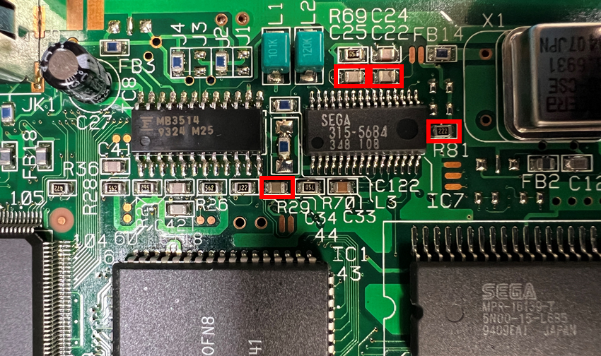
Top Side Component RemovalRemove FML, 32X, PSG Components
Remove the components boxed in red below. R81 is optional, but makes connecting PSG easier (make sure to solder the d-right jumper if you do this!).
Remove RGB Output Components
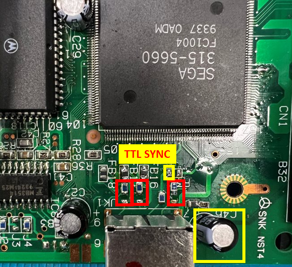
Remove the components boxed in red. The components in yellow must be removed if CVBS restoration is not desired.
NOTE: Some revisions of the CDX have traces connecting the pads of the jumper. If this is the case, either cut the trace between the pads, or lift encoder pins 21-23.
Remove Cart to CD/PCM audio mixing components
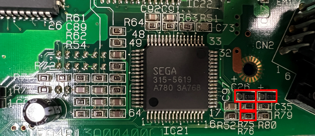
Remove the components shown in red, and replace R75 and R76 with 4.7K 0603 or 0805 size 1/8W (or better) resistors.
Remove FMR and PSG AC Coupling Capacitors
Remove the components boxed in red.
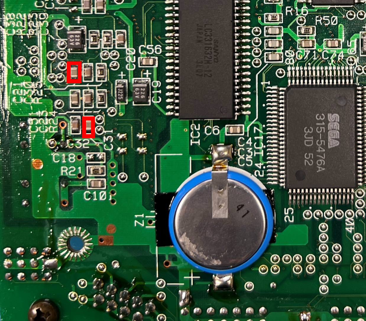
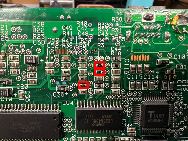
Remove RGB Encoder Input Resistors
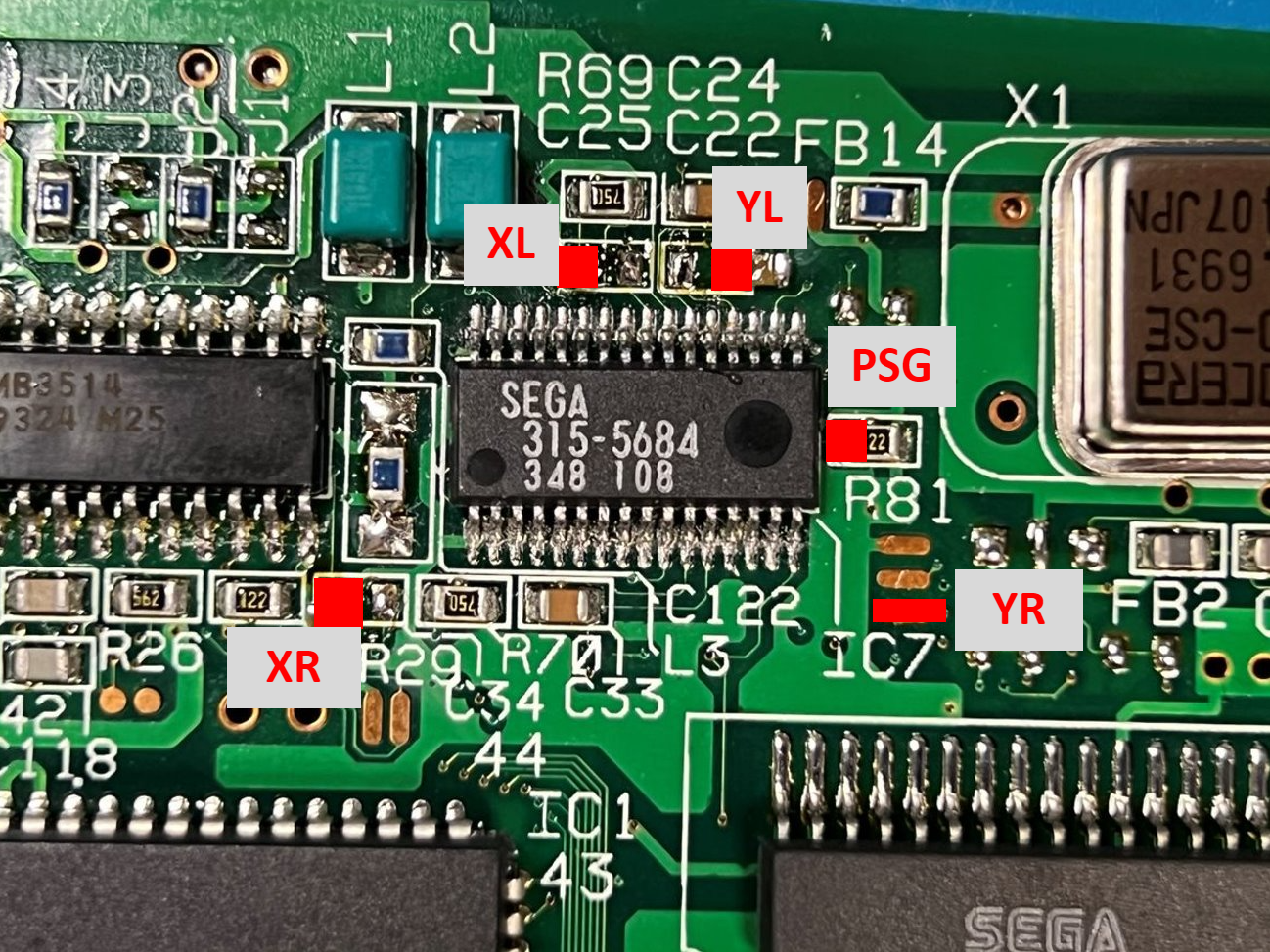
Audio Input Connections
Connect the 3BP audio input pads to the points labeled below. Take note that there is NO input for "CL" or "CR."
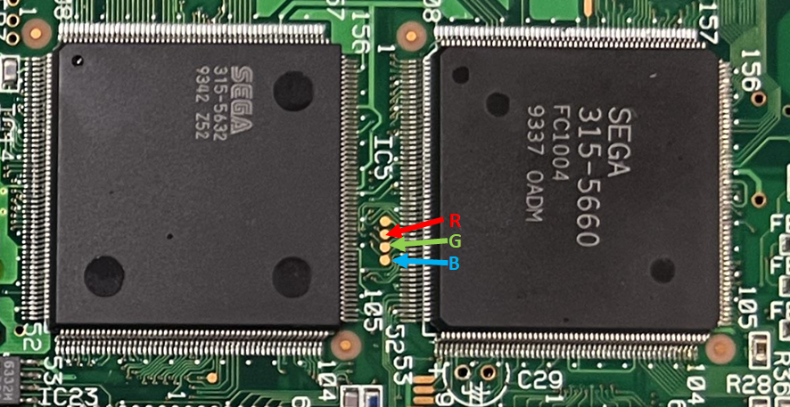
RGB Input Connections
Connect the 3BP RGB input pads to the points labeled below. Refer to the image shown in component removal above for TTL Sync if CVBS restoration is not desired.
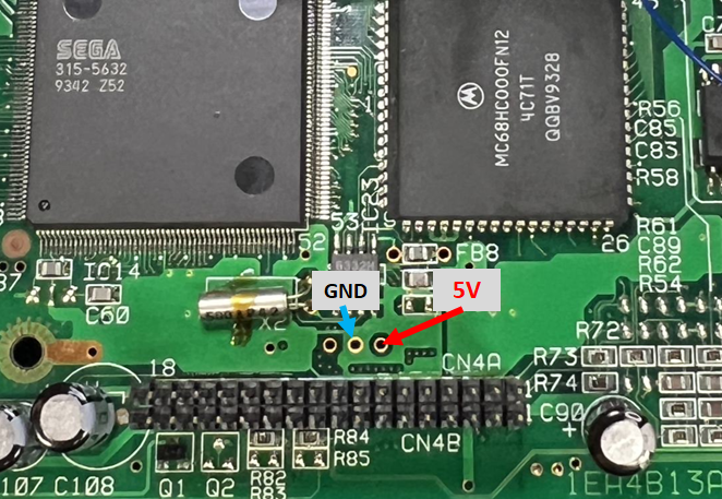
5V and GND Input Connections
Below are suggested connection points for 5V and GND. Other points may also be suitable.
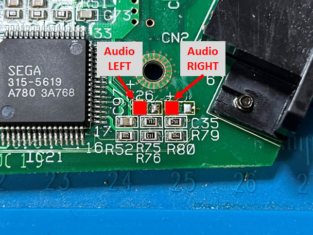
Audio Output Connections
Connect the 3BP Left and Right audio outputs to the points shown below.
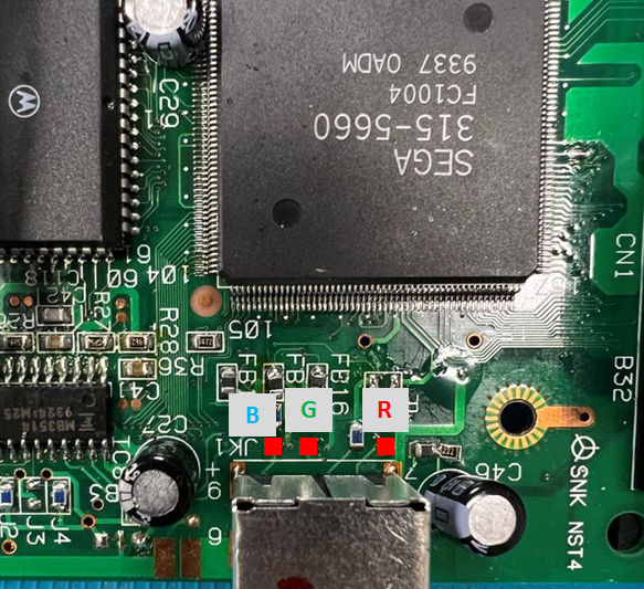
RGB Video Output Connections
Connect the 3BP RGB outputs as shown below. If not restoring CVBS, connect the "S75" output pin to the through hole for C46(-).
If not restoring CVBS, the installation should be finished at this point. If not, see the next step.
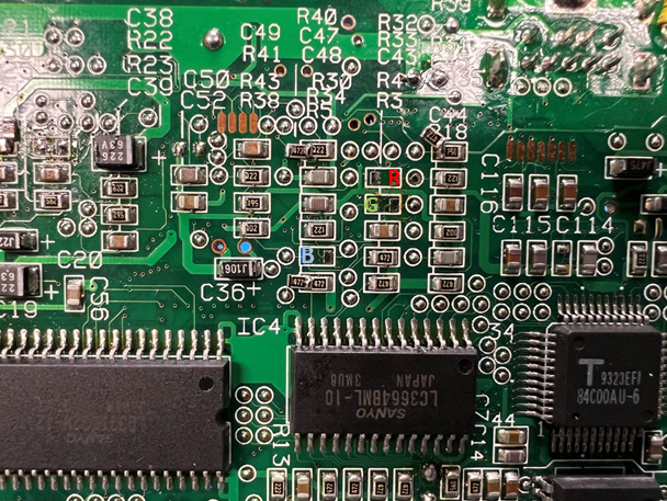
CVBS Restoration Points
If restoring CVBS, use the points indicated below. The 3BP V2Plus has 511 ohm resistors connected to the "R0,"G0" and "B0" pads. Otherwise, use a value between 470 and 511 ohms to connect the RGB output to the pads indicated below.
Below is an example installation of the 3BP, but not necessarily the only correct way to do one.