The New-Style SNES, also known as the SNES Jr., SNES mini or SNS-101, only has composite video output in stock form but can be easily modified for RGB output. Because it uses the same S-RGB video encoder chip as later model 1 SNES consoles (including 1CHIP models), RGB output can be easily added in by wiring up the unused red, green, blue and composite sync outputs of the S-RGB to their respective pins on the multiout connector. While a bypass amplifier board can provide slightly better video quality, this modification can be done very inexpensively and still produces clear and sharp RGB output. This modification can also be performed on the Super Famicom Jr. as it is almost exactly the same as the New-Style SNES internally with very minor differences.
Materials and Tools
- 4.5 mm gamebit screwdriver
- JIS/Philips head screwdriver
- Soldering iron
- Leaded solder
- Flux (optional but highly recommended)
- 26-30 AWG wire
- Three 75 ohm through-hole or SMD resistors, the lowest tolerance possible
- One 1.74k ohm 0805 SMD resistor or three 1.2k ohm resistors, the lowest tolerance possible (optional)
- One 220 nF or 470 nF 0805 SMD capacitor (optional)
Procedure
- Disassemble the SNES by removing the four 4.5 mm gamebit screws on the bottom. Lift off the top shell and set it aside.
- Undo the seven JIS/Philips head screws securing the motherboard to the bottom shell.
- Note that the two screws on each side of the cartridge port and the one on the multiout are longer than the rest. Do not use these anywhere else or damage to the bottom shell may result. Remove the RF shield and set it aside.
- To get at the S-RGB chip, the heat sink for the 7805 regulator must be removed. Remove the screw on the 7805 itself, then flip over the motherboard and remove the two screws securing the heat sink to the board. Note that these particular screws have spiked washers.
- The S-RGB chip is the 24-pin SMD chip located directly behind the 7805.
- See Figure 1 for what the S-RGB chip looks like.
- Solder four wires to the output pins on the S-RGB chip as shown below. Use a soldering tip that's extremely thin, as well as very thin solder. Make sure to tin each pin and each wire before trying to solder them together. Using flux can also help this process. Red is on pin 20, green on pin 22, blue on pin 24, and composite sync on pin 18.
- See Figure 2.
- Carefully route the wires around to the underside of the board where the multiout pins are. If you have desoldering equipment, it is recommended to clear out the filled vias for the unused RF modulator and route the wires through the cleared vias for a cleaner install.
- See Figure 3.
- Replace the heat sink, starting by screwing it back to the motherboard and then screwing the 7805 back on. There should still be enough clearance for the wires connected to the S-RGB.
- See Figure 4.
- With the motherboard upside down, begin wiring the RGBS signals to the multiout. Start by soldering one end of a 75 ohm resistor to multiout pins 1 (red), 2 (green) and 4 (blue). Either through-hole or SMD resistors can be used, with the latter providing a lower and slightly cleaner profile. The wire for composite sync can be soldered directly to pin 3. Note that this is a TTL sync signal and cannot be used directly on some devices.
- See Figure 5.
- For testing, the motherboard can be placed on a non-conductive, non-slip surface or the console can at least be partially reassembled. If done properly, the SNES should now be outputting a bright and clear image through RGB.
- If the image is too bright or washed out, the brightness fix (detailed below) can be performed.
- If ghosting or ringing is noticeable, capacitor C11 can be swapped out for a different value. Any value between 220 nF and 470 nF can be used to reduce ghosting.
-
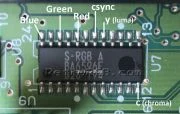 Fig. 1. The S-RGB video encoder chip with RGBS and S-video output pins labeled.
 -
 Fig. 2. Red, green, blue and composite sync (yellow) are wired up to the S-RGB chip.
 -
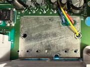 Fig. 3. The unused vias for an RF modulator are repurposed in this install to route the RGBS wires to the underside of the board.
 -
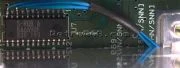 Fig. 4. Enough room exists under the heat sink to route the wires without them being crushed.
 -
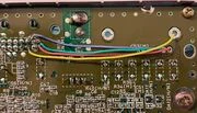 Fig. 5. A completed RGB install using SMD resistors. Note that 82 ohm resistors were used in this particular mod to help bring down the brightness that 1CHIP consoles are known for.
Brightness Fix
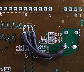
If the resulting image from the RGB mod is too bright or washed out, two types of fixes can be performed to adjust the brightness to a more acceptable level. For a simple fix, resistor R3 (normally 1.6k ohm) can be swapped with an 0805 1.74k ohm resistor. If this is not available, three 1.2k ohm resistors can be used to pull down the RGB signals coming from the S-CPUN ASIC as shown in the image above.