The NESRGB is a video modification board designed by Tim Worthington to improve the video quality of the NES and Famicom. Released in 2013, it was the first RGB output solution for the NES/Famicom that did not require scavenging the RGB PPU from a PlayChoice-10 or Vs. board.
The following information and images have been gathered from Tim's website, with their permission.
Description
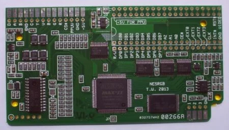
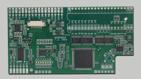
Most unmodified NES and Famicom consoles only support composite and RF (radio frequency) video output, with the original Famicom and top loader NES only having RF output. The NESRGB is an internal mod that adds RGB and S-video outputs to the NES and Famicom. As of version 5, it also adds YPbPr component output.
The mod features a user-selectable palette system that allows the user to change the color scheme of the video output to suit their preference. For more information about NES palettes, see FirebrandX's NES Palette Project page.
Features
- Generates RGB, YPbPr component and S-video signals, passes through composite video from PPU (as of version 5)
- Previous NESRGB versions generated S-video and composite from an RGB video encoder chip, and required an external board for YPbPr; the NESRGB had to be turned off for the original composite video output from the PPU
- No latency (video timing is maintained)
- Built in audio and video amplifiers
- Compatible with NTSC and PAL consoles
- Compatible with NES, Famicom, AV Famicom, and Twin Famicom consoles
- User selectable color palettes for RGB and component via OSD
- Upgradable firmware via JTAG programmer
Technical Details
The NESRGB board contains a CPLD (Complex Programmable Logic Device) that utilizes the NES's PPU (Picture Processing Unit) and CPU to generate an RGB video signal.
Jumpers (NESRGB version 4)
J1 - palette select mode (Open = select palette with switch/closed = select palette with controller)
J2 - palette bank select (open = bank 1, palettes 1-3/closed = bank 2, palettes 4-6 (ignored if J1 is closed))
J3 - power source select (open = external power/closed = internal power (i.e. use the Famicom/NES internal reg.))
J4 - color encoding format (open = NTSC/closed = PAL)
J5 - luma trap frequency (open = PAL/closed = NTSC)
J6 - reset polarity (open = negative (Famicom/NES top loader)/closed = positive (NES front loader))
J7 - PPU type (open = NTSC/closed = PAL)
J8 - Sync Select (open = TTL/closed = 75ohm)
J9 - THS7374 LPF (open = disabled/closed = enabled)
J10 - de-jitter timing correction (open = disabled/closed = enabled)
J11 - LED indicator (open = enabled/closed = disabled)
Note About Jitter
The timing of the NES/Famicom's video signal is slightly unusual and runs slightly under the standard 60 Hz in an attempt to reduce video artifacting. However, this signal is not compatible with all modern displays and may cause some flickering at the top of the screen. Original versions of the NESRGB did not address this and so required a "de-jitter" mod when used on sensitive displays. Beginning with hardware version 2, the NESRGB incorporates a de-jitter function in its firmware. Instructions on how to add a de-jitter mod to older NESRGB revisions can be found here on Tim Worthington's website. As of hardware version 5, the de-jitter feature can be accessed via the OSD (on-screen display).
Note About Hardware Version 5
Version 5 was introduced in April 2026 and is a near-total redesign that incorporates a number of new features, which are detailed here.
NESRGB Errata
As with every electronic devices, issues are discovered and solutions for these issues are made available. NESRGB is no different. Tim publishes NESRGB errata on his site:
Materials Required
- Phillips head screwdriver
- 4.5 mm gamebit screwdriver (required for NES top loader and AV Famicom)
- Soldering iron, solder, flux, wire, and wire stripper
- Desoldering gun (not totally required, but highly recommended as it makes removing the PPU much easier)
- Drill with step bits (required if adding additional connectors)
Installation
Front Loading NES
See the official written documentation.
Original Famicom
See the official written documentation.
AV Famicom
See the official written documentation.
There is also an AV Famicom quick-solder board (QSB) and an additional process to remove jailbars as noted on the LaserBear website.
Top Loading NES
See the official written documentation.
Twin Famicom
See the official written documentation.