The Wii "Sensor Bar" is a fairly inaccurate name, as the bar itself isn't a sensor. It's just 2 IR LEDs that the Wiimote itself uses to sense where it is pointed relative to the bar's position on the TV. Because of the simplicity of the Wiimote sensing mechanism, it's entirely possible to replace the sensor bar in case you either don't have one or due to an incompatibility with either the TV being used or due to natural lighting. This article will cover a few possible ways the sensor bar could either be modded to be more compatible, or replaced with even the simplest household items.
The Candle Method
 | Be careful when playing with candles. An unattended candle can quickly start a house fire or damage your equipment. Do not leave a candle burning without supervision and have a fire extinguisher on hand just in case. |
Yes, it is entirely possible to replace the sensor bar with candles. All you have to do is position them a safe distance from your TV decently close to each other. The sensitivity setting on the Wii may need to be adjusted due to the flames IR emission being more erratic than typical IR LEDs. Candles are a cheap, easy way to replace a sensor bar that is either broken, or lost. Plus, scented candles can improve a room's scent.
Despite the ease of this method, your mileage may vary as candles can be different from one to the next. It's best to use stick candles which wick and flame isn't surrounded by glass. The size of the wick, which effects the size of the flame is also important. You don't want candles that produce either too small or too large of a flame, or the Wiimote may not sense the IR light correctly and cursor movement may be erratic.
The candle method is great for someone who just needs to navigate the Wii menu before moving to using the Wiimote's buttons, or someone who doesn't have electronics experience necessary to make a sensor bar.
Third-party sensor bars
Numerous third-party alternatives are being sold as of December 2025, including many that use the standard Wii pin-out, USB-powered models, and battery-powered ones. Mayflash Limited even sells the Dolphinbar for computers which acts both as the IR source and a dedicated bluetooth adapter.
Making your own sensor bar.
Due to the simplicity of the sensor bar's construction, it's rather trivial for a hobbyist to make a sensor bar out of regular components. Employing the use of a breadboard, soldering isn't necessary.
The sensor bar is just made of a few IR LEDs in series, 2 pairs of which are running in parallel to the voltage outputted by the port on the Wii. A resistor is wired between each pair of LEDs in series and the positive voltage to prevent the LEDs from burning out.
The circuit is fairly simple even for an amateur. The circuit can be powered either using power from the sensor bar's port, or from one of the Wii's USB ports. AA batteries could also be used if portability is a concern, but not recommended due to requiring constant replacement. Your choice of power supply is important to take in consideration as that will change what resistance value (measured in Ohms) your resistors will need to be.
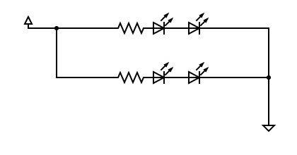
There's many different calculators out there to decide what value your resistors will need to be, and it depends on the values the manufacturer provides on how to get the LEDs to light. Typically you'll need to know the LEDs voltage drop, the forward current, and the amount of LEDs you use in series. You can also calculate it yourself, the equation is R = (Vcc - V) / C where R is the resistance you'll need measured in Ohms, Vcc is the voltage provided by your power supply, V is the voltage required by the LEDs and C is the current of the LEDs, measured in Amps. If you use multiple LEDs in series, then just multiply the voltage required by the amount of LEDs you use. If the resistance value calculated is not a resistor typically made, go with one that's higher but close enough to the value you need. It's better to have more resistance than necessary rather than not have enough and burn out your LEDs.
The circuit diagram on the right is a visual example of what your circuit should look like. You can solder your LEDs together with wire but a breadboard is preferable as you can swap out the LEDs easily should you accidentally burn them out. Plus, if you use 2 small breadboards for each series of LEDs, you can space them apart to give you more distance if your TV is larger or farther away from you. Just run the positive and ground wires between the power rails of the breadboards then plug the power supply into either one.
If you decide to use the Wii's sensor bar port to power your homemade one, you'll most likely need a broken sensor bar to salvage the cord from. It's more preferable to just use a USB port on the Wii which outputs 5V, as opposed to the sensor bar's 7.5V.