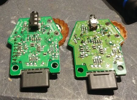
This guide details how to modify an Xbox Live Communicator to add a 3.5mm TRRS headset jack. Please note this should be a last-resort option, as adapter cables are fairly cheap and easy to find. Anyone with novice soldering skills should have no issue doing this modification.
The original guide was created by Harcroft, redone here with permission.
 | If your headset is high impedance, you could damage the communicator and/or your volume on the headset could be too low to be usable. Likely, the single channel output was designed to drive a single low resistance (8Ω-ish) headphone speaker, not two higher impedance speakers. |
Removing the Old Jack
- Remove the 2 screws and open your communicator. Put aside the shell for now.
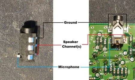
- There are 5 solder points holding the current 2.5mm headset jack in place. The top two are ground, the left and bottom two are for the microphone and the bottom right one is the single audio channel. Using the method of your choice below (or another method), carefully remove the original 2.5mm jack, avoiding pulling the pads off of the board.
- Add solder to the existing joints (and Chip Quik if available), insert a precision screwdriver into the jack, then heat up the solder points in rapid succession while very gently lifting up with the screwdriver.
- Use hot air (and Chip Quik if available).
- Dremel the body of the jack to expose the pins, then desolder the pins one at a time.
- Remove as much old solder as possible so the new jack can sit flush against the board. A good quality desoldering wick and flux is ideal for this as it will remove the little bumps that a desolder vacuum can miss.

Old jack in place 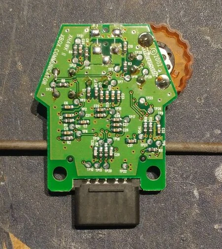
Jack removed 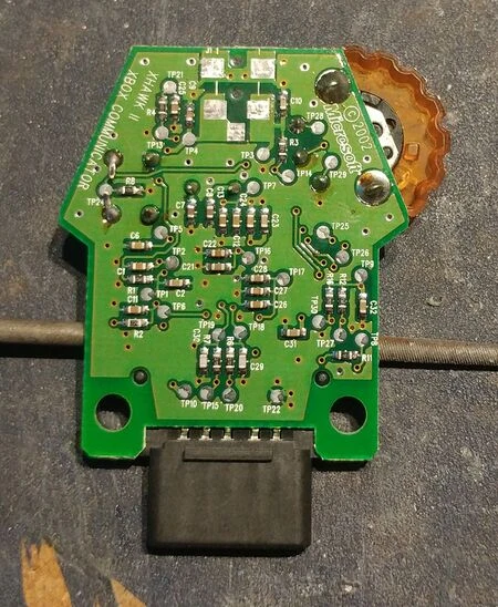
Pads cleaned up
Installing the New Jack
- Inspect the new jack you will be using. If you've purchased a different one than listed in the parts list, verify the pinout before proceeding. Make sure you buy a surface mount jack, a through-hole jack will not fit.
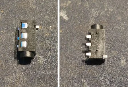
- Use a sharp knife, file, or some other cutting implement to remove the lower index pin as shown here.
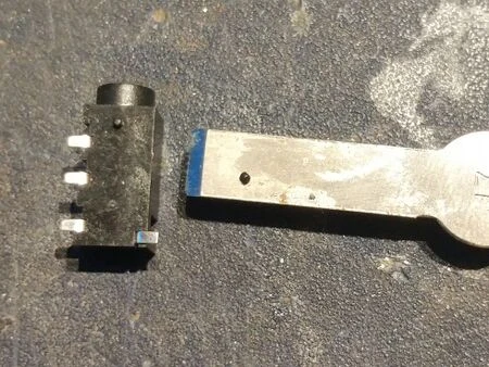
- Test fit the new jack on the circuit board. the index pin should go through the top index hole. Not all of the pads will line up perfectly. Forgive the crappy soldering on the controller connector, that is factory soldering from Microsoft.
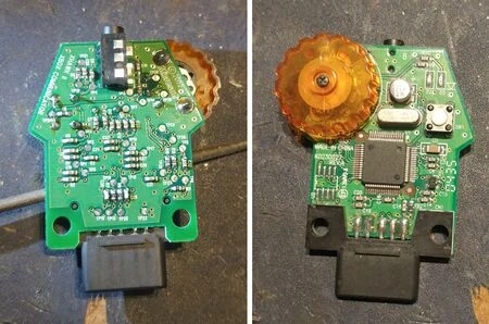
- Right and left views of the fit. These views should help us know where to create new pads to solder to.
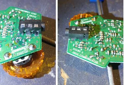
- For the best possible fit and connections you're going to have to scrape some solder mask off from the areas shown. You can use a sharp knife, a file, a precision screwdriver or any other fine instrument that will allow you to scrape off the areas shown without scraping off solder mask from any other traces. Be careful to not scratch the large ground plane just below the bottom 2 new solder pads. Be careful not not to scratch the copper layer right off the board.
- It's not recommended to use a fiberglass scratch brush or any other mass solder mask removal method as you do not want to remove any solder mask from areas you are not trying to connect to. The inaccuracy of a scratch brush will cause problems. The bottom left pin will be overhanging the ground plane solder mask so again do not damage that solder mask.
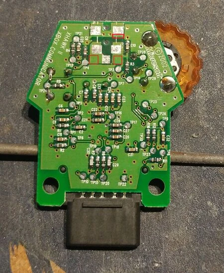
- It's not recommended to use a fiberglass scratch brush or any other mass solder mask removal method as you do not want to remove any solder mask from areas you are not trying to connect to. The inaccuracy of a scratch brush will cause problems. The bottom left pin will be overhanging the ground plane solder mask so again do not damage that solder mask.
- Once the areas are scratched off, apply some flux to the fresh copper pads.
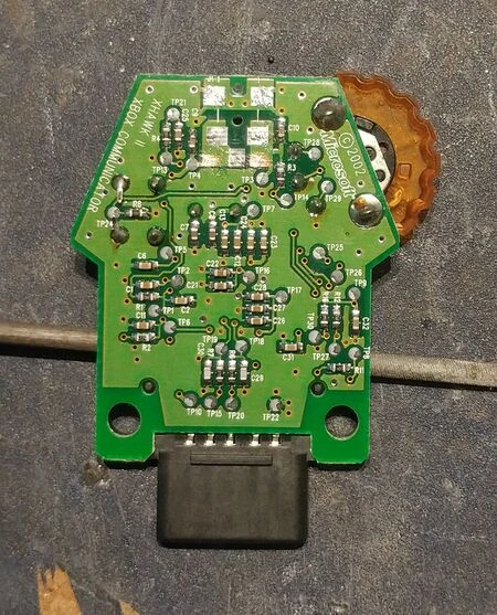
- After lining up the new jack with the one remaining index pin, solder a single leg down so you can adjust the angle and position easily until you are satisfied with the angle and position of the new jack.
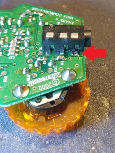
- Once you are happy with the positioning, solder down the rest of the legs. Be careful not to connect the pads on the board and legs on the new socket to anywhere they are not supposed to be connected to.
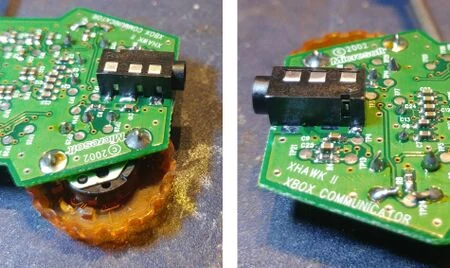
Shell Modification
- To fit the wider opening on the new jack you will need to use a drill bit to bore out the width of the hole on the casing. Somewhere between 3/64" to 1/4" should be the right expanded size. (7/32 is reported to fit well) The plastic is quite thin so this can be done by hand fairly easily. Start small and work your way up.
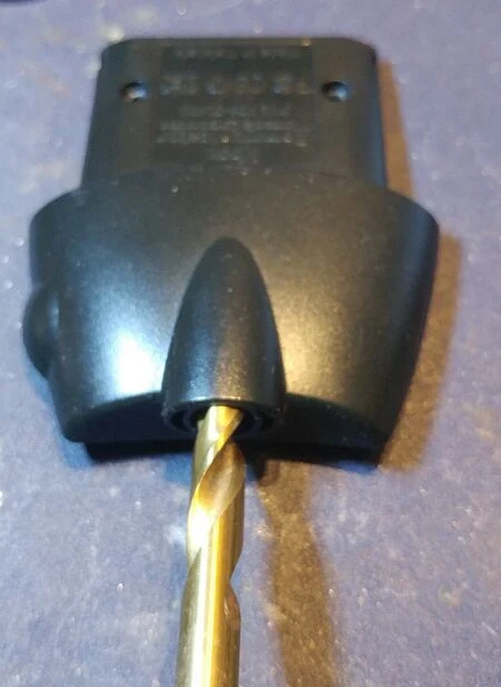
- Bore out the hole until the drill bit moves smoothly in and out of the wider opening.
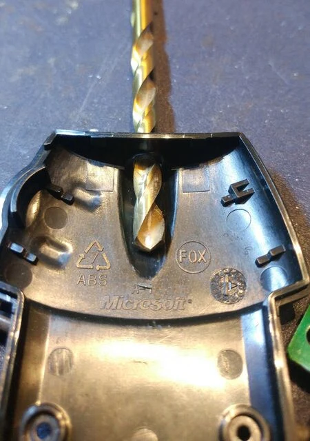
- For a proper fit inside the curved bottom of the Xbox Communicator housing you may need to file off the upper edges of the 3.5mm jack. You may want to use a generic hobby file, moving slowly to not damage the circuit board. This should only take a couple minutes to file the connector enough to fit comfortably inside the OEM housing. This step may not be necessary for you, but may be preferable to for a clean look without adding extra strain to the screws or clips that hold the housing together.
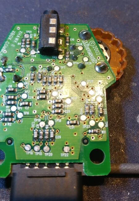
- The finished product. This is after going a little too large with a 1/4" drill bit. As mentioned earlier, start small and work your way up.
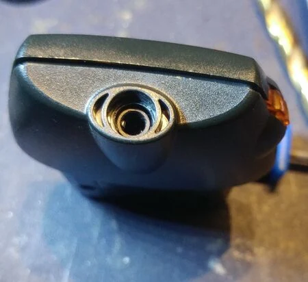
Extra Information
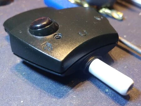
- Often headsets will have a very wide housing adjacent to the TRRS connector, so you may need to find an extension that fits, trim the rubber or plastic housing around headset male TRRS end, or replace the end of your headset entirely.
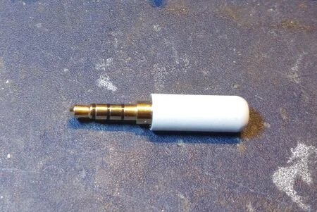
- Whichever method you use to connect a headset to your new 3.5mm TRRS Xbox Communicator, it's recommended to use a connector like this. They are inexpensive and fit nicely into the communicator with the long neck behind the TRRS connections.
- For anyone curious about the exact pinout of these jacks, here is a quick MS paint diagram.