 | This process is dangerous and potentially can brick or fry your Xbox. It involves soldering a very small contact, so it is recommended to be experienced with soldering before proceeding. |
The OpenXenium chip is a low cost open source chip created by Ryzee119. It is essentially a recreation of the Xenium chip that is simple to install. The full hardware/software source can be found on this page. This guide is a modification of KingLuxor and xbmcmodsforxbox’s OpenXenium install guide.
OpenXenium makes use of XeniumOS, whose wiki page can be found here.
'How to Install' video by MrMario2011 can be found here
Features
Software
OpenXenium chips can run the original Xenium OS or PrometheOS (preferred).
Xenium OS features
- Plays all backups, homebrew, debug executables, and original imports
- Supports the LBA48 Hack (max 2TB HDD support)
- In Game Reset (IGR)
- Auto patches new media flag titles
- Works on all regions
- Software controlled BIOS bank switching (any BIOS combinations that fit into 1mbyte of flash memory [4x256k, 1x512+2x256k, 2x512k, 1x1mbyte])
See the XeniumOS page for more detail.
Hardware features
- Support for all Xbox version, 1.0 through 1.6b
- Instant boot to a chosen BIOS using the power button
- Boot to XeniumOS or PrometheOS via eject button
- Ability to boot from the onboard BIOS (colloquially known as TSOP booting). This will completely disable OpenXenium and release D0/LFRAME(1.6) to boot the Xbox as if it is stock
- All the standard features in Cromwell/XeniumOS/PrometheOS (EEPROM tools, Hard drive tools, FTP/SMB Server etc.)
- Three general purpose outputs. These are normally bit banged as an SPI master (MOSI, CLK, CS) with the most common use an LCD, however could support any SPI peripheral in theory
- Two general purpose inputs. On a Xenium, these may be intended to be MISO lines to complement the SPI interface but could be used for any 3.3V digital logic
- Three outputs are connected to an RGB LED (or an external user added RGB LED)
- Reserved memory on the flash chip for non-volatile storage of an EEPROM backup and XeniumOS settings
- If you bridge the two recovery pins, on power up it will attempt to boot the XeniumOS recovery BIOS if available. This functions the same as a genuine Xenium modchip
- Simulated LFRAME abort mechanism (Ref Intel LPC Interface Spec Rev 1.1 Section 4.3.1.13) for a v1.6 console to prevent the Xyclops responding to the MCPX LPC Memory Read requests during boot and conflicting with an external LPC memory peripheral. This is generally accepted to be better than shorting LFRAME the ground constantly, which some traditional LPC memory add-ons do
Required Materials
- Soldering iron and solder - fine tip is preferable
- 30 AWG wire
- Pliers
- Desoldering braid or desolder pump (if LPC port is filled with solder)
- A 7x2 male pin header, or two 7x1 pin headers (if not already supplied with the modchip)
Installation
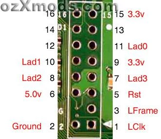
- Disassemble your Xbox and remove the motherboard. Determine the motherboard revision, as the following steps will depend on it.
- If the LPC port is filled in, you will need to desolder the holes using a desolder pump or desoldering braid.
- Use a pair of pliers to pull pin 4 out of the LPC header. The shorter side of the pins is the side which will be inserted into the LPC holes.
- Motherboard revision 1.6/1.6b: Solder five wires to the edges of the LPC ports, as shown in the following diagram. This is known as an "LPC rebuild".
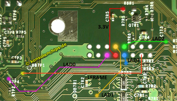
LPC Rebuild diagram
- Motherboard revision 1.6/1.6b: Solder five wires to the edges of the LPC ports, as shown in the following diagram. This is known as an "LPC rebuild".
- Insert the supplied LPC header into the LPC port, with the shorter side of the pins entering the holes. Make sure you have inserted it so that it is using pin 0 and 1. Temporarily tape it in place using electrical tape, and flip the board over. On the underside of the motherboard, touch each pin, and it’s hole to fill it with solder and attach the header in place. Remove the electrical tape and insert the modchip into the LPC header.
- You will need to follow the next steps for soldering, depending on your motherboard revision. It will help to dab a small amount of flux on the contact points and soldering tip.
- Motherboard revision 1.0-1.4: Solder D0 on the motherboard to D0 on the chip. You will need to scrape the surface of the D0 point on the motherboard, as it has a clear solder mask coat on top of it. If you don’t have fine tools or confidence in your soldering skills, the alternate point on the back of the motherboard is easier to solder to than the front side one.
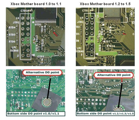
Top-side points for both 1.0/1.1 and 1.2-1.4 motherboard types
- Motherboard revision 1.6/1.6b: Connect D0 on the chip to the nearby pad marked "C2" on the chip.
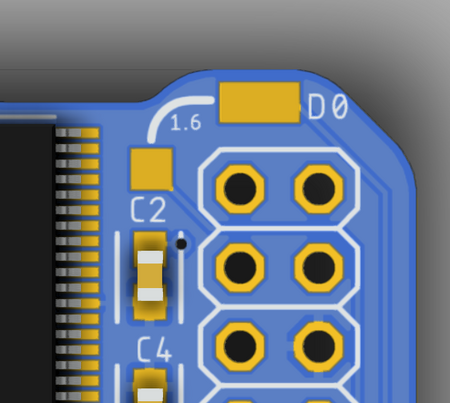
OpenXenium solder pads for enabling the LFRAME connection on the LPC for 1.6 motherboards
- Motherboard revision 1.0-1.4: Solder D0 on the motherboard to D0 on the chip. You will need to scrape the surface of the D0 point on the motherboard, as it has a clear solder mask coat on top of it. If you don’t have fine tools or confidence in your soldering skills, the alternate point on the back of the motherboard is easier to solder to than the front side one.
- Plug back all components, hook Xbox up to a TV, and turn it on to test functionality. If successful, it should show "Welcome to XeniumOS". For usage instructions, see the XeniumOS page.
Troubleshooting
- If you receive any error codes, see the Error Codes page for help.
- If you end up with a clock loop, try connecting the Xbox to your network so it can update the time via NTP or using Auto Installer Deluxe to update the modchip BIOS.