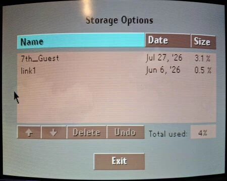
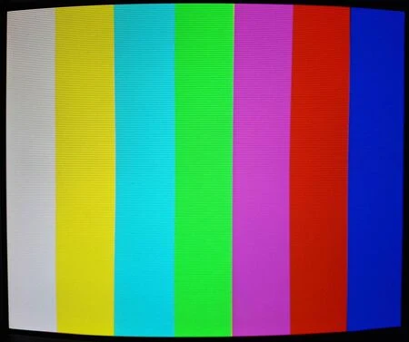
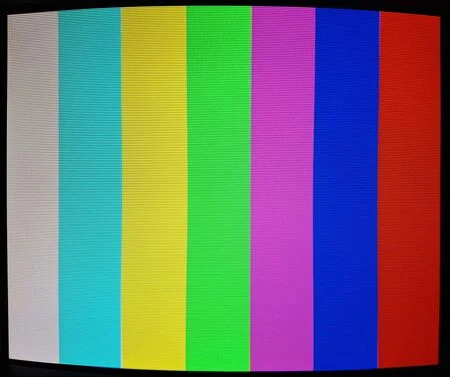
As long as your NTSC CD-i has the Sony CXA1145P or CXA1145M chip (Mono II and earlier motherboards), this mod will work. Some PAL boards may have the RGB SCART built-in already.
Required Materials
You'll need a few tools for this mod:
- Soldering skills
- Torx screwdriver set to open the CD-i case and internals
- Philips head screwdriver
- Soldering iron / solder
- Thin gauge wire
- Four (4) 75 Ohm resistors, the lowest tolerance possible.
- Four (4) 220uF/16v capacitors
- RGB output port to match your RGB cable (any port will work, e.g. an 8-pin mini DIN)
Instructions
- Start by removing the top cover: Remove the two torx screws on each side and the top three screws in back:
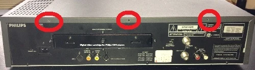
- Next, remove the outer screws that contain the expansion socket. These screws were one size larger torx than the case screws:
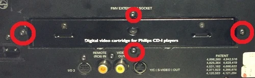
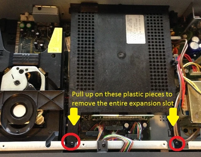
- Before you can remove the expansion socket, remove the two screws on top, then pull up from the area by the top screws to release the socket:
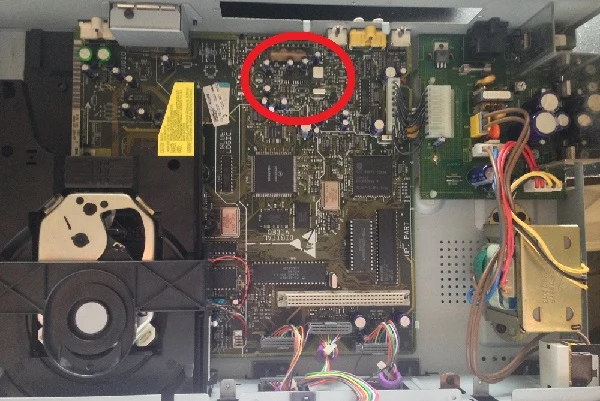
- You'll find the Sony CXA chip underneath the expansion slot:
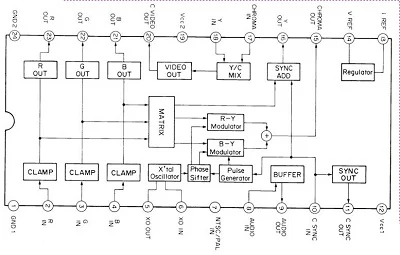
- Solder R, G, B and CSYNC (please see the note about CSYNC below) directly to the chip, as shown here:
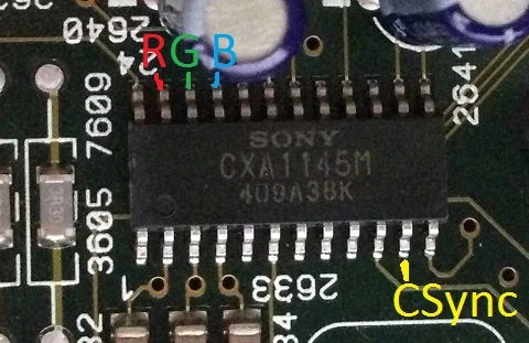
- Here's the actual chip diagram, in case you're interested (click for full-sized):
- Next, choose a mounting location for your RGB port. Options include:
- Removing the RF adapter and use an 8-pin MiniDIN mounted where the RF adapter was. This allows the mod to be 100% reversible, without any cutting.
- Mounting the RGB port on top of the RF adapter box. This requires the ability to drill through metal.
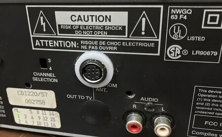
Mounted in place of the RF adapter 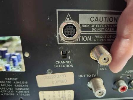
Mounted on top of RF adapter
- Run all four video lines to the output. Make sure each line has the following (order does not matter):
- A 220uF/16V capacitor with the positive side connected to the output port.
- A 75ohm resistor.
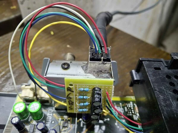
- Find a ground point to solder to your connector. There's no "special" place to get ground, anywhere will do (just verify with your multimeter). If installing the port on top of the RF adapter, you can solder it to the AV port to act as ground and keep it in place.
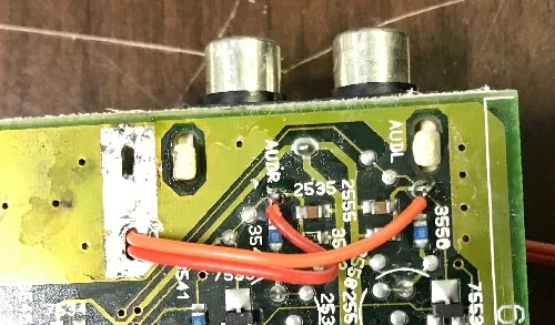
- If your RGB connector routes audio through it, wire that in as well:
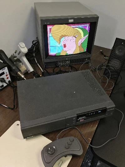
Results:
Troubleshooting
If colors seem to be wrong, check that you have the ground pin on the connector connected to ground. Otherwise, boot into the Service Shell, choose the "Test Image" option, and check that the color bars are correct. If they aren't, you may have the color signals swapped.