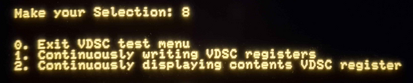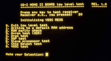
The Philips CD-i has a low-level test menu accessible via the I/O 2 (or "Input 2") port on the back using a serial cable.
Building the Cable
You will need to connect 5 wires, plus one additional for ground, from an 8-pin mini-DIN to a connector of your choice. Do not connect pins 1 or 8, as they are not needed. Below are two example standards for 9-pin and 25-pin connectors for the PC end, taken from this image.
| Signal Function | CD-I mini-DIN # | CD-i Input/Output | PC 9-pin # | PC 25-pin # |
|---|---|---|---|---|
| Not connected | 1 NC | - | - | - |
| Receive Data | 2 RXD | Input | 3 TXD | 2 TXD |
| Transmit Data | 3 TXD | Output | 2 RXD | 3 RXD |
| Data Terminal Ready | 4 DTR | Output | 6 DSR | 6 DSR |
| Ground | 5 GND | - | 5 GND | 7 GND |
| Clear to Send | 6 CTS | Input | 7 RTS | 4 RTS |
| Request to Send | 7 RTS | Output | 8 CTS | 5 CTS |
| +5V (not needed for serial) | 8 +5V | - | - | - |
Using the Menu
- Connect the serial cable to your serial device or USB-serial adapter.
- Set your terminal to use the following settings:
- VT100 mode
- 9600 baud
- 8/1/N (8 data bits, 1 stop bit, no parity bit).
- Screen wrapping on
- Terminal emulation set to standard ANSI
- On your serial-connected device, hold spacebar while powering on the CD-i. If successful, you should see the low level test menu.
Menu Options
0. Exit Low level test
Continues the boot process to allow the CD-i to boot as normal.
1. Writing to a default RAM address
(no picture)
2. ROM parity check
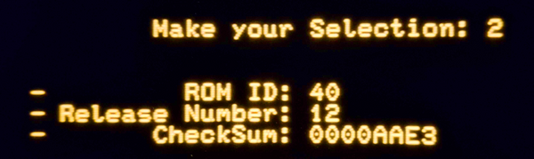
3. Nvram test (32K)
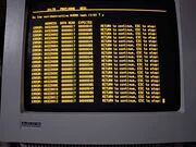
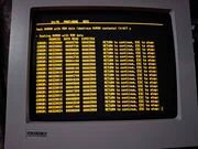
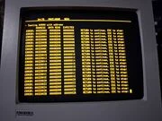
This test can be used to verify the functionality of your NVRAM or a FRAM mod.
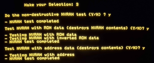
If your NVRAM is malfunctioning, you will see the actual test results as follows:

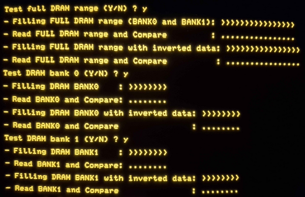
4. Dram test
5. DSP test

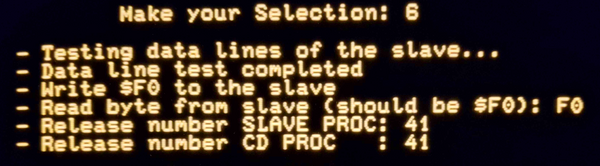
6. Slave processor test
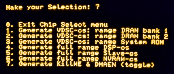
7. Chip select test
8. VDSC test