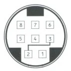
The CD-i has a menu to run various tests accessible via bridging pins 2 and 3 of the IO connector. This can be achieved by using a female-female jumper wire across the two pins or by using a 8 pin mini DIN connector and bridging the two pins in the plug.
There are different versions of the Service Shell, with different options and different labels on buttons. For example, the version included on the CDI601 and CDI602 have a DUART test and they refer to the laser lens cartridge as the "sledge".
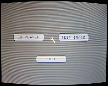
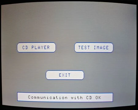
CD PLAYER
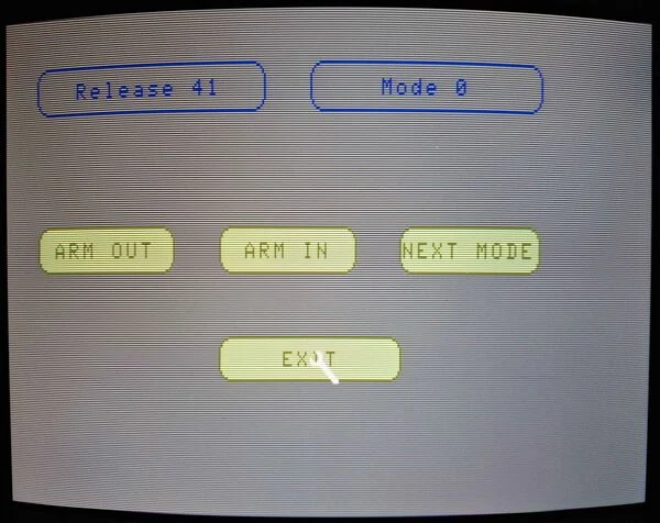
Mode 0
Mode 0 allows you to test the CD player's mechanical arm by being able to move the CD lens inwards or outwards. The CD drive processor's firmware version is displayed in the top left corner.
Mode 1
Mode 1 tests the ability to focus the laser onto a disc. A disc must be present in the console, otherwise it will always show "NO FOCUS" and after 16 attempts to focus, it will return to the Mode 0 menu.
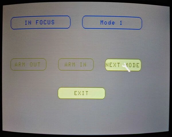
Mode 2
Mode 2 rotates the CD turntable. If an error occurs, it will return to the Mode 0 menu.
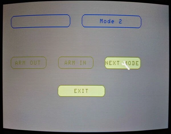
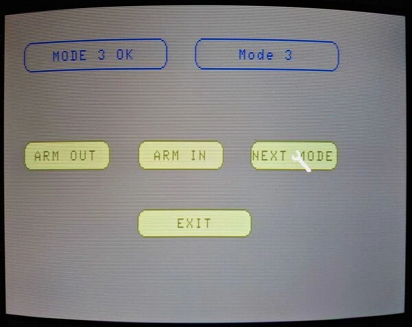
Mode 3
Mode 3 allows you to select ARM IN or ARM OUT to move the CD lens in small jumps as long as the button is held.
TEST IMAGE
A color bars image is shown. The image should match the below one.

DUART TEST
Present only on the CDI601 and CDI602, it allows you to select which I/O port to test the UART functionality of. Once a port is selected, you will be asked to connect a test plug into that port and it will test to check that pins 7 and 8 are connected and pins 2 and 3 are connected. After pressing a button, it will start the check.
Error Messages
Error messages are displayed in the format of A5 XX0000 with XX being the error code.
| XX | Error meaning |
|---|---|
| 2 | Focus error |
| 3 | Radial error |
| 5 | Off error (TL stays low for 50 msec) |
| 6 | Jump error |
| 7 | Subcode error, no vaild subcode in 3 sec |
| 8 | TOC error: out of lead-in area while reading the TOC |
| 30 | Too many grooves to jump |
| 31 | Search time out |
| 32 | Bin, search error |
| 33 | Search index error |
| 34 | Search time error |
| 37 | Selection error |