 | This is an advanced mod. If care is not taken while removing the original VRAM chips, multiple solder pads and traces can be lifted, which will result in a difficult repair being necessary. The key to avoiding this is patience. |
The ColecoVision uses the TMS9928/9929 VDP, which requires the use of eight chips to provide 16 KB of video RAM (VRAM). Specifically, the ColecoVision uses eight 4116 DRAM chips which require three voltage rails to operate (5V, 12V and -5V). These chips run fairly hot and are prone to failure, not helped by the ColecoVision's unreliable power switch which can cause some of these voltage rails to provide intermittent power or nothing at all.
Because 4116 DRAMs have been obsolete since the early 1980s and are fairly difficult to source, a common solution is to replace these with 4164 DRAMs, which only use a single voltage rail (5V) and run much cooler, providing more reliable operation. This also means that a dirty power switch is far less likely to cause problems such as glitchy graphics or no display.
Overview
Replacing the VRAM chips is fairly simple, but is not a straight swap due to the ColecoVision's triple voltage design. First, the 12V and -5V rails must be severed from the VRAM circuit, which is accomplished by removing two inductors (L2 and L3). Once this is done, 5V is then wired up to where the 12V rail was on the VRAM circuit, as the 4164 takes 5V where the 4116 had 12V. The 4164 has an extra address line (A7) not used on the ColecoVision, and must be pulled high when not in use. Fortunately, this address line connects to where 5V was on the 4116, so no further modification is required here.
Note that 41256 DRAM chips can be used instead of 4164s, but 5V must be wired to the -5V rail of the VRAM circuit since these chips have another address line (A8) not used on the ColecoVision. While both the 4164 and 41256 provide considerably more memory than the 4116, ColecoVision games are not coded to use more than the original 16 KB. While it is possible to wire these address lines into the ColecoVision's system bus, this will provide absolutely no benefit.
Materials and Tools
- Phillips head screwdriver
- Multimeter
- Soldering iron (preferably temperature-controlled)
- Desoldering braid or desoldering gun (the latter is highly recommended for this procedure)
- Tweezers (optional)
- Eight 4164 or 41256 compatible DRAM chips (speed is not important; be careful when purchasing these online as fakes can be found on eBay or Aliexpress)
- Eight 16-pin dual wipe DIP sockets (optional but recommended)
- Hookup wire
- Wire cutters and stripper
- Leaded solder
- Flux (optional but highly recommended)
Procedure
- Flip over the ColecoVision console and remove the eight screws securing the case. The front panel is slightly clipped onto the bottom shell and may provide some resistance when removing the top shell. Tilt the top shell towards the front while gently prying the bottom of the front panel.
- Remove the screws securing the top RF shield. Some consoles may have a thick grounding strap on the shield which will need to be desoldered.
- Remove the motherboard from the bottom case, setting the bottom case aside.
- Desolder inductors L2 and L3, which are large brown or orange components located in the center of the board near the SN76489 sound chip. L2 is for the -5V rail and L3 is for the 12V rail. (See Figs. 1 and 2)
- Connect the right-hand side pad of L3 to the nearest 5V point using a component lead or short length of wire. (See Fig. 3)
- If you are using 41256 chips, connect the right-hand side pad of L2 to 5V as well.
- Desolder all eight of the 4116 chips. It is best to use a desoldering gun to remove these, but be very careful not to apply heat for too long as the pads are fragile and can be easily lifted. (See Figs. 4 and 5)
- Alternatively, the 4116s can be cut out by using a flush cutter to snip the pins close to the chip package, then using a soldering iron and a tweezer to help extract the severed pins. A desoldering gun or braid can then be used to clear out the vias.
- Solder the chip sockets into the board, paying close attention to the orientation of the notch, which must be facing the right-hand side of the board. The solder joints must be smooth ramps, so make sure not to use too much or too little solder. (See Fig. 6)
- Note that using sockets isn't totally necessary, but will make replacing the VRAM easier in the future in case of possible VRAM failures or if a chip is accidentally inserted backwards.
- Insert the new VRAM chips into the sockets, being careful not to bend any pins. Make sure that all the chips are inserted firmly in the sockets.
- Before testing with the power plugged in, use a multimeter to check that pins 8 and 9 of each VRAM chip are connected to 5V. This can be done by flipping the power switch on (which connects the 5V and 12V rails to the system) and checking for continuity between these pins and the white wire on the power connector. Make sure that you have not accidentally shorted either the 12V or -5V rails to 5V, as the system uses these two voltages on other circuits.
- If you used 41256 chips, check that pin 1 of each chip is also connected to 5V.
- It is very important that you do this continuity check to avoid frying the new VRAM chips with 12V or -5V.
- Once the continuity check is done, reassemble the console to the point where it can be tested. The console should function normally with no scrambled graphics or black screen. Once testing is finished, fully reassemble the console.
- If you get scrambled graphics or text, or no screen at all, double check your work. Make sure each pin of every socket is soldered properly with no bridges, and that each chip is inserted all the way into its socket.
-
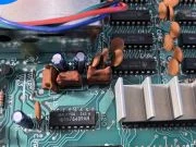 Fig. 1. Inductors L2 and L3 are located in the center of this image and must be removed.
 -
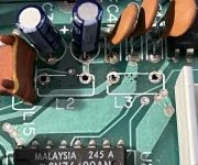 Fig. 2. L2 and L3 have been desoldered.
 -
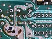 Fig. 3. The right pad of L3 is now connected to 5V, providing the new VRAM chips with the 5V they require.
 -
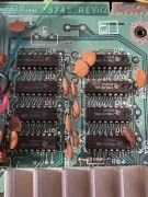 Fig. 4. The original 4116 chips.
 -
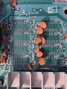 Fig. 5. All eight VRAM chips have been desoldered and the board is ready for the replacements.
 -
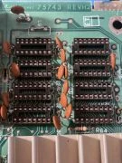 Fig. 6. Sockets in place for the new VRAM chips. Note that L9 was removed and bridged as part of a completely unrelated mod.
 -
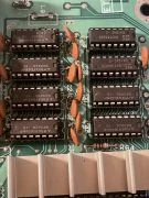 Fig. 7. The new VRAM chips in place. Note that two of the chips are of a slightly different type and speed, but this does not matter.