The only audio/video output that the ColecoVision possesses is RF, but it can at least be modified for composite video and audio out. Various methods exist for performing an AV mod on a ColecoVision, each with varying degrees of complexity. All of these modifications involve tapping the composite video signal generated by the LM1889 modulator chip, which is inside the RF modulator.
Ben Heck Mod (Transistor-Based)
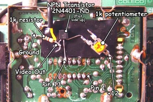
Developed by prominent modder Ben Heckendorn in the early 2000s, this modification uses an NPN transistor as a buffer with a 1k ohm pulldown resistor and a 1k ohm potentiometer to control the voltage going into the transistor. It provides a decent quality image and because it only consists of a handful of common components, is fairly easy and inexpensive to build. However, it requires some adjustment depending on the display it's connected to, and is not recommended for consoles that are moved between different displays or devices. The original guide also left out a 47 uF capacitor and 75 ohm resistor, which are needed for proper impedance matching and DC offset filtering.[1]
Materials and Tools
- Phillips head screwdriver
- TO-92 NPN transistor (either a 2N3904 or 2N4401 will do)
- 1k ohm resistor
- 75 ohm resistor
- 1k ohm trimmer potentiometer
- 10 uF 10V electrolytic or tantalum capacitor
- 47 uF 10V electrolytic or tantalum capacitor
- Soldering iron (preferably temperature-controlled)
- Leaded solder
- Flux (optional but recommended)
- Hookup wire
- Wire cutters and stripper
- Kapton tape
- Choice of output connector(s)
Procedure
- Flip over the ColecoVision console and remove the eight screws securing the case. The front panel is slightly clipped onto the bottom shell and may provide some resistance when removing the top shell. Tilt the top shell towards the front while gently prying the bottom of the front panel.
- Remove the screws securing the top RF shield. Some consoles may have a thick grounding strap on the shield which will need to be desoldered.
- Remove the motherboard from the bottom case, setting the bottom case aside.
- Pop open the top shield in the RF modulator with a pry tool or flathead screwdriver, which will expose the bottom of the modulator board.
- Solder the base pin (center pin) of the NPN transistor to pin 13 of the LM1889, which is the fourth pin from left. The LM1889 is located in the center of the modulator board.
- Lay down a strip of kapton tape underneath the transistor to prevent the video circuit that is being built from shorting on the modulator board.
- Make sure that the flat side of the transistor is facing up.
- Solder one end of the 1k ohm resistor to the emitter pin (left pin) of the transistor and the other end to ground.
- Take the 1k trim pot and solder the top pin to 12V. The bottom right pin goes to the collector (right pin) of the transistor. The bottom left pin is not connected and can be snipped off to avoid a possible short.
- Solder one end of the 75 ohm resistor to the junction of the emitter and 1k ohm resistor.
- On the other end of the 75 ohm resistor, solder the positive lead of the 47 uF capacitor. Video output will come from the negative lead of the capacitor.
- Audio can be taken from pin 2 of the connector going between the modulator board and motherboard. These pins are lined up vertically on the right side of the modulator. Connect a 10 uF filter capacitor for audio, with the positive lead connected to pin 2 of the modulator connector and the negative lead going to the audio output.
- Wire up the output connector(s) of your choice to video, audio and ground. Reassemble the console enough for testing.
- Ben's original guide recommends taking audio directly from the SN76489 PSG chip, but doing it this way will not allow audio from expansion port devices to be passed through, such as from the Expansion Module #1 and Super Game Module. Tapping audio from the RF modulator ensures that all audio will be passed through.
- Wire up the output connector(s) of your choice to video, audio and ground. Reassemble the console enough for testing.
- Adjust the potentiometer using a flathead screwdriver, which controls the voltage going into the transistor. The image should be bright and clear without too much color fringing or washed out colors.
Op-Amp Mod
This modification is based on an LM318 op-amp, and while it is more complex than the Ben Heck mod, it provides a slightly higher quality image and does not require any post-installation adjustments. While simple enough to be built from scratch, kits are available from vendors such as Console5 and RetroFixes.
Materials and Tools
- Phillips head screwdriver
- LM318 op-amp
- Two 10k ohm resistors
- One 27 ohm resistor
- One 75 ohm resistor
- Two 10 uF 10V electrolytic or tantalum capacitors
- 47 uF 16V electrolytic or tantalum capacitor
- Soldering iron (preferably temperature-controlled)
- Leaded solder
- Flux (optional but recommended)
- Hookup wire
- Wire cutters and stripper
- Kapton tape
- Choice of output connector(s)
Procedure
- Assemble the amplifier PCB according to the directions, if it came with any. Otherwise, refer to the silkscreen on the amp board.
- Flip over the ColecoVision console and remove the eight screws securing the case. The front panel is slightly clipped onto the bottom shell and may provide some resistance when removing the top shell. Tilt the top shell towards the front while gently prying the bottom of the front panel.
- Remove the screws securing the top RF shield. Some consoles may have a thick grounding strap on the shield which will need to be desoldered.
- Remove the motherboard from the bottom case, setting the bottom case aside.
- Pop open the top shield in the RF modulator with a pry tool or flathead screwdriver, which will expose the bottom of the modulator board.
- Solder a wire from pin 6 of the connector going between the modulator board and motherboard. These pins are lined up vertically on the right side of the modulator. Connect the other end to the video input pad of the amp PCB.
- Solder a wire from any ground source to the ground pad of the amp PCB.
- Solder a wire from any 12V source to the 12V input of the amp PCB.
- Place the amp PCB in a clear area where it will not short on any components. Use a small length of double-sided foam tape to secure it.
- Audio can be taken from pin 2 of the modulator connector. Connect a 10 uF filter capacitor for audio, with the positive lead connected to pin 2 of the modulator connector and the negative lead going to the audio output.
- Wire up the output connector(s) of your choice to video, audio and ground. Reassemble the console enough for testing.