 | This page is a work in progress. It's possible that not all features or settings are covered at this moment, and additions will be made as new features are introduced. This page is intended for documentation and assistance with the RetroTINK-4K family of upscalers. If you are looking for information on using other retro upscalers, please refer to their wikis and documentation. |
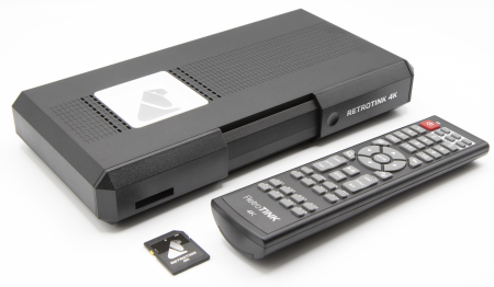
The RetroTINK-4K and RetroTINK-6X are an advanced family of video scalers from RetroTINK LLC. Building on the functionality of the RetroTINK-2X and RetroTINK-5X, the RetroTINK-4K/6X offer high-end video scaling and processing at resolutions up to 4K60. There are four models of the RetroTINK-4K/6X
- RetroTINK-4K CE - The baseline white model offering a wide and extensive range of features.
- RetroTINK-4K Pro - The original black model with a more powerful FPGA, enabling the use of more advanced features (described below).
- RetroTINK-6X CE - A budget friendly version of the 4K CE that caps resolution at 1440p60 and removes the HDMI input.
- RetroTINK-6X Pro - A yet-to-be-released model that aims to bring more function than the 6X CE.
This page serves the instruction manual for all four models, as well as a How To Guide to help you understand how best to use each of its functions.
Below is a table mapping out all the pages on Console Mods that cover the RetroTINK-4K/6X:
| Main Page | Firmware Repository | System Specific Settings | SD Card Inventory |
|---|---|---|---|
| The page you're reading right now! Covers all operations of the RetroTINK, including Additional Guides, Community Resources and FAQ / Troubleshooting. | An external GitHub repository with downloads for every officially released RetroTINK firmware. | Details the settings you may want to consider when first connecting a console to the RetroTINK. | Covers the SD Card's contents, such as Profiles, CRT Mask profiles, and CSCs (Color Correction Profiles). |
Overview
The RetroTINK-4K/6X are the latest evolution of the RetroTINK line of video line doublers and upscalers. For schematics including the dimensions and measures of its casing, see the CAD and Schematics archive.
Below is a list of some standout features:
Output
- HDMI® up to 4K60 (4K models only)
- Flexible output modes including 480p, 1080p, 1440p at various refresh rates
- Custom modelines on the SD card
- Fully buffered video (drop-free on input changes), Gen Locked and Frame Locked sync modes
- HDR10 output with full color correction to Rec. 2020
- High frame rate output modes: 1440p120, 1080p240
- Optional deep color output (10 bits at 4K60 may not be compatible with all displays)
- Up to 8-ch LPCM audio or compressed audio passthrough
Inputs
- Supports for virtually all analog formats:
- HD15 / VGA: RGBHV, RGBS, RGsB, YPbPr, S-video and Composite
- SCART: RGBS, RGsB, YPbPr, S-video and Composite
- Rear RCA: RGsB, YPbPr and Composite
- Front Composite
- Front S-Video
- HDMI® Input supporting up to 1080p60/1200p (CVT-rb) and up to 8 channels LPCM.
- The 6X CE does not include an HDMI input
- Analog audio input sampled at up to 96kHz/24-bit with full gain control
- Optical TOSLINK audio input supporting 2-Ch LPCM or compressed surround
- HDMI® audio supports up to 8-ch LPCM up to 96 kHz or compressed surround
Analog Video
- Automatic gain calibration
- Automatic phase calibration
- Automatic input cropping to trim borders
- Full control of gain, offset and sample rate
- Console specific automatic sample rate detection (experimental feature)
- Support for a wide variety of off-spec arcade and PC boards (may require custom profiles to properly trim and center the image)
- Max input resolution of 1920x1080p60 or 1920x1200p60 CVT-rb
- Robust composite/S-video decoder with multi-region support (NTSC, PAL, PAL-60, SECAM)
Scaling
- Fully flexible, custom cropping and zooming in the horizontal and vertical space independent of other settings
- Automatic aspect ratio correction to 4:3 or 16:9
- Motion Adaptive deinterlacing, including film modes for 3:2 and 2:2 inverse telecine (telecine on Pro model only)
- RoTATE 90 deg CW or CCW, for 240p, 288p and 360p inputs (Pro model only)
CRT Simulation
- Multiple CRT beam profiles
- Fully configurable CRT beam strength and intensity modulation
- Adjustable CRT masks and strength
- Interlaced video simulation with offset scanlines
- LCD simulation patterns that automatically adapt to scaling, including non-integer factors
Image Processing
- End to end RGB pipeline with internal 12-bit precision
- Conventional gamma and approximated modes to minimize quantization error
- Advanced and fully configurable gamma and perceptual quantizer (HDR)
- Advanced color gamut transforms to simulate different display technologies
- Black frame insertion engine with customizable pattern and intensity
- Linear light processing
User Interface
- Advanced OSD menu-based system
- SD Card for storing custom modelines, firmware updates and saving profiles
- Support for over 100,000 profiles
- Custom premium remote control
Product Contents
A new RetroTINK package will come with the following items:
- 1x RetroTINK unit (exact model depends on which was ordered)
- 1x 8GB SD Card, pre-loaded with software and profiles.
- 1x USB-A / USB-C SD Card Reader
- Only the 4K Pro and 6X CE come with this reader.
- 1x Remote Control (exact remote depends on which model was ordered)
- 1x USB-A to USB-C Power Cord
| The package does not include an AC adapter or HDMI® Cable. For power, we recommend using a USB power supply that can output at least 2A at 5V (10W or higher). Please use a power supply by a reputable brand such as Anker or your phone manufacturer. We do not recommend plugging the RetroTINK into the USB ports of your display, as they often do not provide enough power and may result in operation errors. For HDMI®, any HDMI® 2.0 or higher cable rated at 18Gbps or more will work with the RetroTINK. Please make sure you purchase products from reputable vendors. |
Getting Started
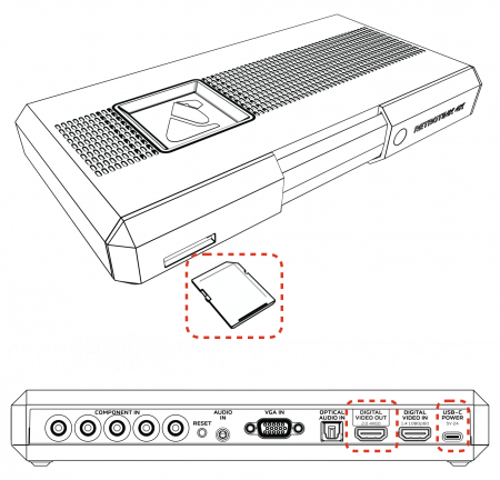
The RetroTINK is designed to be powerful, yet easy to use and quick to set up. Here are some steps to get started using your RetroTINK:
- Insert an SD Card - A card is included with every RetroTINK that includes the firmware and profiles. Please make sure this card is inserted in the device, as it is required for proper operation. If you lose the card or have any issues with it, any SD card, or microSD card with adapter, formatted with FAT32 SD may be substituted. Up to 1TB cards have been tested after having been formatted with this tool.
- Connect to USB-C Power - Connect the RetroTINK to a USB power supply that can output at least 2A at 5V (10W or higher) with the included USB-C power cable.
- Connect HDMI Video Output - Connect an HDMI® cable (2.0 or higher / 18Gbps+) from the RetroTINK output to your display.
- Power on the RT4K - If you haven't done so already, turn the RetroTINK on. Once it's done booting, you should see a solid green light on the front of the unit.
- Confirm HDMI Video Output - By default, the RetroTINK-4K outputs 4K60. If you don't see any picture, confirm that your display supports 4K60, or press the button on the remote that matches the resolution of your display (1080p, 1440p, or 480p). See the Remote and Output sections for more information.
- The 6X models output 1080p by default for compatibility with most displays.
- Video Input - Connect your device's output to any of the RetroTINK's inputs and turn your device on. More information on supported connections can be found in the Inputs section.
- Select Your Input Source - Press the "Input" button at the top of the remote, then choose the port and signal your game system is using.
- Enjoy - Once your video source is visible, you're ready to go! Enjoy the high quality, low latency scaling of the RetroTINK. Time to play the game!
Are you having trouble getting started? Look through this step-by-step guide for troubleshooting your RetroTINK.
Basic Analog Calibration
With your game up and running, you may want to consider two more steps if you're using an analog video source (note that HDMI® video sources do not require calibration):
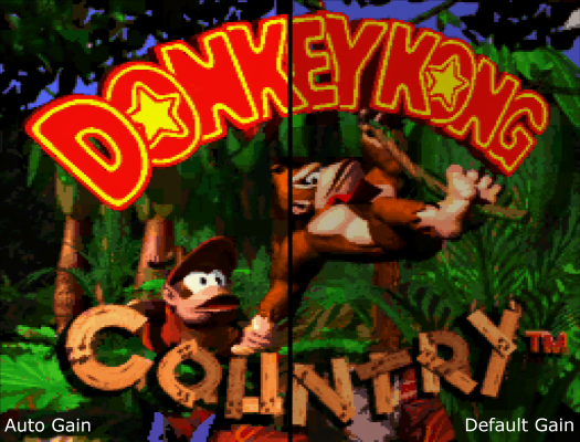 |
Auto Calibrate the Gain - The RetroTINK has a function to automatically calibrate the gain, which works well so long as there's a patch of pure white somewhere on the screen. Gain should be applied on a per-console basis.
Advanced users may want to use the manual gain controls under Advanced Settings > RGB/Component ADC, in tandem with the 240p Test Suite. |
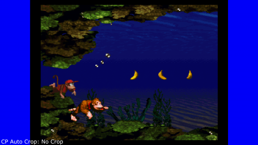 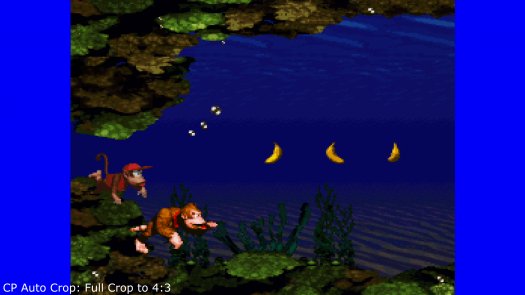 |
Crop the Picture - Cropping the picture is how the RetroTINK scales images to the edges of a screen and centers them. For best results, use a screen that has no black or dark edges. Crops should be applied on a per-game basis.
You can also manually crop and resize the picture if you wish by going to Advanced Controls > Scaling/Cropping. Head to that section to learn more. |
Tweaks, Filters and Beyond
Of course, there is a lot more you can do with your RetroTINK. Here are some more advanced options to explore:
- Update the Firmware
- Choose an Expert-Crafted Optimal Profile
- CRT and Scanline Effects
- Improve Image Vividness with HDR
- Improve Motion Clarity With Black Frame Insertion
Firmware Updates
For firmware notes and downloads, please see the RetroTINK-4K Firmware GitHub page.
Firmware Installation
The RetroTINK can be updated to any firmware (including older firmware), with new releases adding more new features as they are made.
- Power off your RetroTINK and remove the SD card.
- Insert the SD card used for your RT4K into the SD card slot on your computer. If your computer doesn't have an SD card slot, you can connect it using the provided USB card reader (only included with the RT4K-Pro).
- Download the .zip file of the firmware you want from the RetroTINK firmware website.
- Extract the contents of the .zip file (the ".rbf" and "rt4kup.bin" files) to the SD card's root directory. Be sure to replace the existing "rt4kup.bin" file on the SD card, as this is used to determine which firmware to install.
- If you intend to update via the RT4K's menu, do not delete the old *.rbf firmware file. If you do, you'll be forced to update via the Reset button method (see Step 6 below for how to do this).
- Remove the SD card and insert it into the SD card slot on the RetroTINK.
- There are two methods for initiating the firmware installation. The RT4K installs firmware based on the "rt4kup.bin" file.
- Option 1: Power on the RetroTINK, then go to Advanced Settings > OSD/Firmware. In the Firmware update section, select "Check SD Card" to scan for the firmware file, then confirm that you want to install it.
- Option 2: Hold down the blue Reset button on the back of the RetroTINK, then power it on. The firmware installation will begin automatically.
- As of experimental firmware 1.6.0, if you wish to use the reset button method, you must unplug the rt4k from power, hold the reset button, and plug the power back in.
- If the LED blinks red, an install error has occurred. Check the files on the SD card and try again.
- The RT4K will reboot for about 40 seconds, with the front LED flashing pink and then blue. Once done, it will power on again as normal with a green LED. You're done!
| If you can't power on your RT4K or see the LED blink yellow, you've erased your current .rbf firmware file from your SD card. Please make sure both the .rbf and .bin files are on the root of the SD Card, and use the reset button method noted above. |
| CE model only: Support for the RT4K-CE was added in firmware version 1.7.3. To speed up the startup time, it is recommended that you copy only the "rt4kce_#.rbf" and "rt4kup.bin" files to your sd card. The "rt4k_#.rbf" file is not needed. |
All custom profiles, CSC files, banner images, input modes, mask overlays and modelines will be kept, as those are stored on the SD card instead of on the RT4K itself.
Significant New Features
If you've just gotten a RetroTINK, this sections lists the significant features added via firmware updates after launch.
- MiSTer DV1 support for auto-decimating and auto-cropping video output from MiSTer cores.
- Auto-Cropping for HDMI® input sources.
- SEGA Saturn auto-sampling support.
- Interlaced scanlines can now be added to progressive sources.
- Enhanced S-Video via the HD15 port, allowing for improved picture quality compared to the actual S-Video port. (Pro model only)
- Edge Adaptive interpolator to minimize jagged edges when MADI is using Bob deinterlacing. (Pro model only)
- Pass-through of HDR10 and HLG content from HDMI® sources, useful for modern platforms like the PlayStation 4.
- Auto-load DV1 profiles based on reported core name.
- Interlaced output support, such as 480i and 1080i.
- Low resolution OSD mode for 480i and 240p output modes.
- Auto-sleep timer to power off the RT4K after some time with no input detected.
- Option to set power on state.
- Serial communications over HD15 and USB, via virtual serial ports, offer remote control actions.
- SVS (Scalable Video Switch) support, including auto-loading profiles on new input.
- Support for third party remotes.
Pro-Exclusive Features
Thanks to a more powerful FPGA, the RetroTINK-4K Pro offers several features that are unavailable on other models. There are no alternative firmware branches between RetroTINK models: they all use the same firmware.
Below is a list of all features only available on the Pro model, which are explained in more detail in their respective sections further below:
- Higher Input Pixel Width - Other RetroTINK models can accept input sources with up to 2048 horizontal pixels, while the 4K Pro can accept up to 4096 horizontal pixels. Input sources with higher horizontal resolution need to be decimated to fit within the respective maximum supported resolution.
- This only presents an issue with MiSTer FPGA platforms in DV1 mode when Auto Decimate is turned off. Devices in this mode will often send images with widths over 2048 pixels.
- Enhanced S-Video - A unique input option for the HD-15 port that allows S-Video to be processed with sharpness in the order of YPbPr or RGB.
- This ultimately affects unmodified consoles that max out at S-Video, such as N64 or 3DO.
- RoTATE - Allows for the rotation of certain images, useful for arcade boards and vertical shooters.
- IIR LPF Horizontal Blur - A function that approximates the left-to-right horizontal blurring present in some CRTs.
- See the Toshiba AF44 example in the post processing section.
- IIR HPF Horizontal Blur - A function that can be used to clean up the smear on 3 chip SNES consoles.
- xBR Smoothing - Enables the xBR scaling algorithm commonly associated with 2D emulators.
- You may want to look into the various horizontal and vertical kernels in the interpolation section instead.
- Black Frame Insertion is available on both models but the pro has these exclusive features:
- Black Frame Insertion Color - Allows for customization of the colour of the inserted BFI frame.
- Black Frame Insertion Rolling BFI - BFI occurs in sections of the screen rather than one giant black frame. This gives BFI a more accurate representation of the rolling behavior of a CRT
- Motion Adaptive Deinterlacing Controls - Allows for adjustments to MADI, including sensitivity, Noise Threshold, and the Edge Adaptive interpolator.
- Other deinterlacing algorithms are still available and may suit your tastes, but the fine tuning is no longer available.
- Inverse Telecine - Enables IVTC functions to deinterlace 24hz content via 3:2, and 25hz or 30hz content via 2:2. Requires content to be 'telecined' (a special type of interlacing) rather than simply interlaced.
- In short, 3:2 allows for some interlaced content to be viewed as the original 24fps progressive picture. This is useful for movies, which are shot in 24FPS, but are converted to 480i60 for home video.
- 2:2 allows stable 576i50 or 480i60 content created from 576p25 or 480p30 to be viewed at the original 576p25 or 480p30. This is a very niche feature for movies sped up to 25FPS from a 24FPS master and converted to 576i50 for home video in PAL regions. This setting is also largely desirable for unmodified ps2 content. Not every game plays in stable 30fps, and not all 480i60 content is telecined.
- 3D Comb Filter - NTSC composite video can be given a 3D comb filter, reducing rainbow artefacts and dot crawl.
- Digital Audio Resampler - Converts off spec modes such as the Gamecube's 44.042 kHz to standard 48 or 96 kHz.
Remote
| RetroTINK-4K Pro Remote Diagram | |||||||||||
|---|---|---|---|---|---|---|---|---|---|---|---|
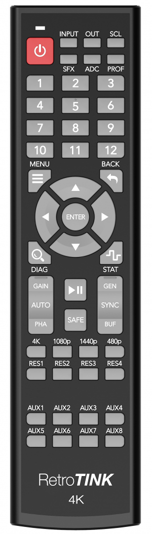 |
Button | Description | IR Code (Addr, Cmd) | Button | Description | IR Code (Addr, Cmd) | Button | Description | IR Code (Addr, Cmd) | ||
| Power | Powers on / off the RT4K | 0x49, 0x1A | 11 | Profile 11 | 0x49, 0x26 | 4K | Switches to 3840x2160p 60Hz | 0x49, 0x30 | |||
| INPUT | Input source selection menu | 0x49, 0x11 | 12 | Profile 12 | 0x49, 0x27 | 1080p | Switches to 1920x1080p 60Hz | 0x49, 0x31 | |||
| OUT | HDMI® Output menu | 0x49, 0x20 | MENU | RetroTINK-4K Main Menu | 0x49, 0x5C | 1440p | Switches to 2560x1440p 60Hz | 0x49, 0x32 | |||
| SCL | Scaling/Cropping menu | 0x49, 0x21 | BACK | Back out to previous menu | 0x49, 0x42 | 480p | Switches to 720x480p 60Hz | 0x49, 0x33 | |||
| SFX | Processing/Effects menu | 0x49, 0x22 | △ | Up | 0x49, 0x18 | RES1 | Custom Output Resolution 1-4.
See Custom Modelines for further explanation. |
0x49, 0x34 | |||
| ADC | HDMI® Receiver menu if HDMI® In is currently displayed
RGB/Component ADC menu if an RGB or Component input is currently displayed SDP Decoder menu if a Composite / S-Video input is currently displayed |
0x49, 0x23 | ◁ | Left | 0x49, 0x57 | RES2 | 0x49, 0x35 | ||||
| PROF | Profiles menu | 0x49, 0x24 | ENTER | Enter | 0x49, 0x53 | RES3 | 0x49, 0x36 | ||||
| 1 | Profile 1 | 0x49, 0x0B | ▷ | Right | 0x49, 0x4F | RES4 | 0x49, 0x37 | ||||
| 2 | Profile 2 | 0x49, 0x07 | ▽ | Down | 0x49, 0x10 | AUX1 | "Vertical Only" Auto Crop | 0x49, 0x38 | |||
| 3 | Profile 3 | 0x49, 0x03 | DIAG | Diagnostic Console screen | 0x49, 0x28 | AUX2 | "Full Crop to 4 by 3" Auto Crop | 0x49, 0x39 | |||
| 4 | Profile 4 | 0x49, 0x0A | STAT | Status screen | 0x49, 0x29 | AUX3 | "Full Crop to 16 by 9" Auto Crop | 0x49, 0x3A | |||
| 5 | Profile 5 | 0x49, 0x06 | AUTO-GAIN | Auto Calibrate Gain | 0x49, 0x2B | AUX4 | 0x49, 0x3B | ||||
| 6 | Profile 6 | 0x49, 0x02 | AUTO-PHASE | Auto Calibrate Phase | 0x49, 0x2D | AUX5 | 0x49, 0x3C | ||||
| 7 | Profile 7 | 0x49, 0x09 | PLAY/PAUSE | Pause current screen | 0x49, 0x56 | AUX6 | 0x49, 0x3D | ||||
| 8 | Profile 8 | 0x49, 0x05 | SAFE | Safe Mode | 0x49, 0x2E | AUX7 | 0x49, 0x3E | ||||
| 9 | Profile 9 | 0x49, 0x01 | SYNC-GEN | Sync Lock - Gen Lock | 0x49, 0x2C | AUX8 | 0x49, 0x3F | ||||
| 10 | Profile 10 | 0x49, 0x25 | SYNC-BUF | Sync Lock - Triple Buffer | 0x49, 0x2F | - | |||||
| RetroTINK-4K CE Remote Diagram | |||||||||||
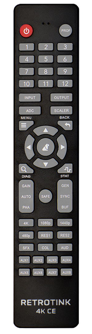 |
Button | Description | IR Code (Addr, Cmd) | Button | Description | IR Code (Addr, Cmd) | Button | Description | IR Code (Addr, Cmd) | ||
| Power | Powers on / off the RT4K | 0x49, 0x1A | MENU | RetroTINK-4K Main Menu | 0x49, 0x5C | RES1 | Custom Output Resolution 1-4.
See Custom Modelines for further explanation. |
0x49, 0x34 | |||
| PROF | Profiles menu | 0x49, 0x24 | BACK | Back out to previous menu | 0x49, 0x42 | RES2 | 0x49, 0x35 | ||||
| 1 | Profile 1 | 0x49, 0x0B | △ | Up | 0x49, 0x18 | SFX | Processing/Effects menu | 0x49, 0x22 | |||
| 2 | Profile 2 | 0x49, 0x07 | ◁ | Left | 0x49, 0x57 | COL | Color Correction menu | 0x49, 0x60 | |||
| 3 | Profile 3 | 0x49, 0x03 | Bunny | Enter | 0x49, 0x53 | AUD | Audio input menu | 0x49, 0x61 | |||
| 4 | Profile 4 | 0x49, 0x0A | ▷ | Right | 0x49, 0x4F | AUX1 | "Vertical Only" Auto Crop | 0x49, 0x38 | |||
| 5 | Profile 5 | 0x49, 0x06 | ▽ | Down | 0x49, 0x10 | AUX2 | "Full Crop to 4 by 3" Auto Crop | 0x49, 0x39 | |||
| 6 | Profile 6 | 0x49, 0x02 | DIAG | Diagnostic Console screen | 0x49, 0x28 | AUX3 | "Full Crop to 16 by 9" Auto Crop | 0x49, 0x3A | |||
| 7 | Profile 7 | 0x49, 0x09 | STAT | Status screen | 0x49, 0x29 | AUX4 | 0x49, 0x3B | ||||
| 8 | Profile 8 | 0x49, 0x05 | AUTO-GAIN | Auto Calibrate Gain | 0x49, 0x2B | AUX5 | 0x49, 0x3C | ||||
| 9 | Profile 9 | 0x49, 0x01 | AUTO-PHASE | Auto Calibrate Phase | 0x49, 0x2D | AUX6 | 0x49, 0x3D | ||||
| 10 | Profile 10 | 0x49, 0x25 | SAFE | Safe Mode | 0x49, 0x2E | AUX7 | 0x49, 0x3E | ||||
| 11 | Profile 11 | 0x49, 0x26 | SYNC-GEN | Sync Lock - Gen Lock | 0x49, 0x2C | AUX8 | 0x49, 0x3F | ||||
| 12 | Profile 12 | 0x49, 0x27 | SYNC-BUF | Sync Lock - Triple Buffer | 0x49, 0x2F | ||||||
| INPUT | Input source selection menu | 0x49, 0x11 | 4K | Switches to 3840x2160p 60Hz | 0x49, 0x30 | ||||||
| OUTPUT | HDMI® Output menu | 0x49, 0x20 | 1080p | Switches to 1920x1080p 60Hz | 0x49, 0x31 | ||||||
| ADC | HDMI® Receiver menu if HDMI® In is currently displayed
RGB/Component ADC menu if an RGB or Component input is currently displayed SDP Decoder menu if a Composite / S-Video input is currently displayed |
0x49, 0x23 | 1440p | Switches to 2560x1440p 60Hz | 0x49, 0x32 | ||||||
| SCALER | Scaling/Cropping menu | 0x49, 0x21 | 480p | Switches to 720x480p 60Hz | 0x49, 0x33 | ||||||
The RetroTINK 4K remote uses the same IR codes as some Oppo devices. If you have an Oppo device and you notice that your RT4K turns on when you use the Oppo remote, you can change the remote code set the Oppo remote uses. See the manual of your Oppo device for more information.
Pause Button
| The pause button is physically exclusive to the RetroTINK-4K Pro remote. The other models can add the functionality by adjusting the remote file with a custom IR code. |
The Remote included with the RT4K Pro model features one function that cannot be accessed anywhere else: the Pause function. Pressing this will pause the on the current frame and mute the audio. This frame will even be remembered if you switch to a different input source and back.
- Perhaps the most useful application of the Pause Button is with the Motion Adaptive Settings. Here you'll be able to adjust the deinterlacing settings and see their effects more easily on a frame in motion, letting you tweak them to your liking more easily.
 | WARNING: There are situations where using the Pause function will have unintended effects, such as when loading a different profile, using the cropping tools, or engaging Inverse Telecine. Other functions, such as Black Frame Insertion, won't be visible at all because they require new video frames in order to work. |
Safe Mode
Safe Mode is an option accessible by pressing the blue Reset button on the back of the unit, or by holding down the "SAFE" button on the remote for two seconds. This causes the following:
- Loads the Default profile.
- Sets the input to HDMI® In.
- The RT6X CE defaults to the front composite input.
- Sets the output to 480p at 59.94 Hz.
Safe Mode is intended for use in troubleshooting, as any display that supports HDMI® should be required to support 480p60. It's also handy as a fall-back in case you need to return the RetroTINK to a default state for any reason.
Custom Remote IR Codes
Custom IR code sets can be loaded by placing a file named ir_remote.txt in the SD root and turning the RetroTINK on and off once. The new IR codes replace the old codes, the RetroTINK does not listen for both. The file contains one line per button you want to change.
File Format:
<button name>, NEC Address, NEC Command
All numbers are in decimal not hex!
Tip: The status screen on the RetroTINK displays the IR codes of all remotes it detects. The codes shown in the RT4K menu are in hexadecimal and have to be converted to decimal before they can be used in the ir_remote.txt file.
| Button | Name | Button | Name | Button | Name | ||
| Power | IR_RT_PWR | 10 | IR_RT_10 | 4K | IR_RT_4K | ||
| INPUT | IR_RT_INPUT | 11 | IR_RT_11 | 1080p | IR_RT_1080P | ||
| OUT | IR_RT_OUTPUT | 12 | IR_RT_12 | 1440p | IR_RT_1440P | ||
| SCL | IR_RT_SCALER | MENU | IR_RT_MENU | 480p | IR_RT_480P | ||
| SFX | IR_RT_SFX | BACK | IR_RT_BACK | RES1 | IR_RT_RES_1 | ||
| ADC | IR_RT_ADC | △ | IR_RT_UP | RES2 | IR_RT_RES_2 | ||
| PROF | IR_RT_PROF | ◁ | IR_RT_LEFT | RES3 | IR_RT_RES_3 | ||
| COL | IR_RT_COL | ENTER | IR_RT_OK | RES4 | IR_RT_RES_4 | ||
| AUD | IR_RT_AUD | ▷ | IR_RT_RIGHT | AUX1 | IR_RT_AUX_1 | ||
| 1 | IR_RT_1 | ▽ | IR_RT_DOWN | AUX2 | IR_RT_AUX_2 | ||
| 2 | IR_RT_2 | DIAG | IR_RT_DIAG | AUX3 | IR_RT_AUX_3 | ||
| 3 | IR_RT_3 | STAT | IR_RT_STAT | AUX4 | IR_RT_AUX_4 | ||
| 4 | IR_RT_4 | AUTO-GAIN | IR_RT_GAIN | AUX5 | IR_RT_AUX_5 | ||
| 5 | IR_RT_5 | AUTO-PHASE | IR_RT_PHASE | AUX6 | IR_RT_AUX_6 | ||
| 6 | IR_RT_6 | PLAY/PAUSE | IR_RT_PAUSE | AUX7 | IR_RT_AUX_7 | ||
| 7 | IR_RT_7 | SAFE | IR_RT_SAFE | AUX8 | IR_RT_AUX_8 | ||
| 8 | IR_RT_8 | SYNC-GEN | IR_RT_GENLOCK | - | |||
| 9 | IR_RT_9 | SYNC-BUF | IR_RT_BUFFER | - |
Example 'ir_remote.txt' to tell the RT4K to use the RT5X standard remote:
IR_RT_PWR, 128, 129
IR_RT_MENU, 128, 131
IR_RT_UP, 128, 56
IR_RT_DOWN, 128, 64
IR_RT_LEFT, 128, 55
IR_RT_RIGHT, 128, 57
IR_RT_OK, 128, 19
IR_RT_BACK, 128, 39
Remote mapping file to use the RetroTINK-5X Premium Remote on your RetroTINK 4K: ir_remote_(RT5X_Premium_Remote).zip
LED Light
The RetroTINK has a front LED light that changes color and behavior to convey information about its operation to the user. Below is a chart for LED light behavior and what they mean.
| Color | Description |
|---|---|
| No Light | No power. No electrons, no business. |
| Slow Red Pulse | Sleep. Unit must be turned on for use. |
| White | The unit is booting up, but is not yet ready for use. |
| Green | The RetroTINK is on and ready for operation. |
| Yellow Flash | System files not found on SD card during boot. Check to see if the SD card is correctly inserted, that it has the .rbf system file, and that the rt4kup.bin file matches it. |
| Purple-Purple Flash | The RetroTINK is updating the firmware. |
| Blue-Blue Flash | Firmware update is successful. |
| Red Flash | Firmware update error. Check the files on the SD card and try again (the unit is NOT bricked). |
Inputs
The RetroTINK features inputs for a wide variety of signals and connector types, which can be selected in the Input Selection menu. These options can be accessed by pressing the Input button at the top of the remote, or by pressing the Menu button and choosing "Input Selection".
| The RetroTINK-4K Pro model can accept input sources with up to 4095 horizontal pixels. Other models accept up to 2048 horizontal pixels, which is only a concern for ultrawide resolutions. None can accept 4K resolution input. |
HDMI®
 |
The RetroTINK supports many resolutions digitally, up to 1920x1080p60 or 1920x1200p60 CVT-rb. Unlike standard consumer equipment, the RetroTINK can tolerate and adapt to arbitrary and off-spec resolutions.
It does NOT support higher resolution inputs, including 1440p and 4K input. If these inputs are fed into a RetroTINK, it will not display anything. |
| The RetroTINK-6X CE does not include HDMI input. For HDMI input, consider a higher end model or a DAC |
Front
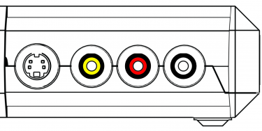
The RetroTINK offers S-Video (over Mini-DIN) and Composite (over RCA) inputs in the front (which can be concealed / revealed by moving the sliding panel). The red and white RCA jacks are stereo audio inputs. Red/White front audio inputs are active when either the Front Composite or S-Video input is selected (assuming audio input override is not used). Only connect one input at a time to the front inputs. If you want to connect sources for both video types, you can use one of the other inputs on the side or back in addition to the front input.
| Front Inputs | ||
|---|---|---|
|
Composite | To use Composite video, use the yellow RCA jack for video (CVBS/Composite) and the Red/White RCA jacks for right and left audio input, respectively. |
| S-Video | To use S-Video, use the Mini-Din for video (Y/C S-Video) and the Red/White RCA jacks for right and left audio input, respectively. | |
Rear RCA
The rear RCA jacks support YPbPr (Component), RGsB, and CVBS (aka Composite) inputs.
| Rear RCA Input | ||
|---|---|---|
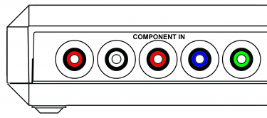 |
YPbPr | The Rear RCA input supports YPbPr (Component video). The maximum resolution supported is 1920x1080p at 60fps, or 148.5Mhz.
|
| RGsB | The Rear RCA input also supports RGsB (aka RGB Sync on Green), a flavor of RGB that sends the sync alongside the Green signal. The maximum resolution supported is 1920x1080p 60fps, or 148.5Mhz
| |
| CVBS on Green | Composite video (CVBS) can be used with the Rear RCA inputs. The maximum supported resolution is 480i.
| |
SCART
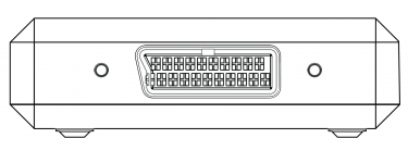
The SCART port is the large rectangular input on the right-hand side of the device. SCART has many different options for video input using the same connector design, as it was designed to carry a wide array of them using a single cable.
| Two M4x0.7 thread screw-holes sit on either side of the SCART port, 70.4mm apart from each other relative to their centers. These allow for a user-made solution to give a more secure fit for the SCART cable (similar to the HD-15 port's screw-holes). The RetroTINK-6X CE does not have these threads, though the holes are still there. |
| SCART Input | ||
|---|---|---|
 |
RGBS (75 ohm) | RGBS is a form of RGB where sync is sent through a discrete line. The RetroTINK accepts the following RGBS signal formats via SCART: Composite Sync (attenuated), Sync-on-Luma, and Sync-on-composite. They all work by sending information down the Red, Green, Blue, and "Sync" lines. The maximum resolution supported is 1920x1080p 60fps, or 148.5 MHz |
| RGsB | RGsB sends sync down the green input, using only 3 cables. This RGB format is notably used by the PS2 when in 480p mode via SCART. The maximum resolution supported is 1920x1080p 60fps, or 148.5 MHz | |
| YPbPr | YPbPr is sent through the Green, Blue, and Red pins, respectively. The maximum resolution supported is 1920x1080p 60fps, or 148.5 MHz | |
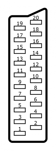
| CVBS on Pin 20 | Composite video sent through Pin 20, usually through a composite to SCART adapter or if your cable uses sync-on-composite video and you wish to use composite instead of RGB. As with all composite signals, only 240p/480i/288p/576i signals are supported. | |
| CVBS on Green | Composite video can be sent through the Green pin. This would be useful if you use a component (YPbPr) to SCART adapter, just plug composite (yellow) into the Y RCA jack (Green). As with all composite signals, only 240p/480i/288p/576i signals are supported. | |
| Y/C on Pin 20/Red | S-Video (Y/C) can be sent down Pin 20 (sync) and the Red pins. You will need a S-Video to SCART adapter. As with all S-video signals, only 240p/480i/288p/576i signals are supported. | |
| SCART Jack Pinout | |||||||
|---|---|---|---|---|---|---|---|
 |
Pin # | RGBS (75 Ohm) | RGsB | YPbPr | CVBS on Pin 20 | CVBS on Green | Y/C on Pin 20/Red |
| 1 | Unused | ||||||
| 2 | Audio In - Right | ||||||
| 3 | Unused | ||||||
| 4 | Ground (Audio) | ||||||
| 5 | Ground (Blue) | ||||||
| 6 | Audio In - Left | ||||||
| 7 | Blue | Blue | Pb | Unused | |||
| 8 | Unused | ||||||
| 9 | Ground (Green) | ||||||
| 10 | Unused | ||||||
| 11 | Green | Green+Sync | Y | Unused | CVBS | Unused | |
| 12 | Unused | ||||||
| 13 | Ground (Red) | Ground (C) | |||||
| 14 | Unused | ||||||
| 15 | Red | Red | Pr | Unused | Chroma (C) | ||
| 16 | Unused | ||||||
| 17 | Ground | ||||||
| 18 | Ground (Sync) | Ground (CVBS) | Unused | Ground (Y) | |||
| 19 | Unused | ||||||
| 20 | Sync | Unused | CVBS | Unused | Luma (Y) | ||
HD-15
The HD-15 connector (or VGA connector) is commonly associated with PCs, however it's also famously available for the SEGA Dreamcast.
| Unlike SCART, the HD-15 port does not accept audio. When using HD-15, audio should be input using the RT4K's 3.5mm TRS input (associated with the HD-15 port by default), or the TOSLINK "optical" input. |
| HD-15 Input | ||
|---|---|---|
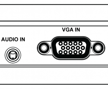 |
RGBHV | RGBHV is a form of RGB where information is sent through 5 lines: Red, Green, Blue, Horizontal Sync, and Vertical Sync. The maximum resolution supported is 1920x1080p 60fps, or 148.5 MHz. This is most common for PC sources. |
| RGBS | RGBS is a form of RGB where sync is sent through a discrete line. The RetroTINK accepts the following RGBS signal formats via HD-15: Composite Sync (75 Ohm attenuated or TTL), Sync-on-Luma, and Sync-on-composite. They all work by sending information down the Red, Green, Blue, and "Sync" lines. The maximum resolution supported is 1920x1080p 60fps, or 148.5 MHz | |
| RGsB | RGsB sends sync down the green input, using only 3 cables. This RGB format is notably used by the PS2 when in 480p mode via SCART. The maximum resolution supported is 1920x1080p 60fps, or 148.5 MHz | |
| YPbPr | YPbPr is sent through the Green, Blue, and Red pins, respectively. The maximum resolution supported is 1920x1080p 60fps, or 148.5 MHz | |
| CVBS on Hsync | Composite video sent through the horizontal sync line. As with all composite signals, only 240p/480i/288p/576i signals are supported. | |
| CVBS on Green | Composite video can be sent through the Green line. As with all composite signals, only 240p/480i/288p/576i signals are supported. | |
| Y/C on Green/Red | S-Video (Y/C) can be sent down Green (Y) and the Red (C) pins. As with all S-video signals, only 240p/480i/288p/576i signals are supported. | |
| Y/C on G/R (Enc.) | An Enhanced S-Video mode only available on the HD-15 connector, and only on the Pro model. (Y/C) can be sent down Green (Y) and the Red (C) pins. As with all S-Video signals, only 240p / 480i / 288p / 576i signals are supported. Sampling and Luma calibration is done in the RGB/Comp. ADC Setup menu, and settings noted in the system specific settings apply. | |
| HD-15 Jack Pinout | |||||||||
|---|---|---|---|---|---|---|---|---|---|
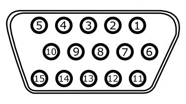 |
Pin # | RGBHV | RGBS | RGsB | YPbPr | CVBS on Hsync | CVBS on Green | Y/C on Green/Red & Enhanced Y/C | Data |
| 1 | Red | Red | Red | Pr | Unused | Chroma(C) | Unused | ||
| 2 | Green | Green | Green+Sync | Y | Unused | CVBS | Luma(Y) | Unused | |
| 3 | Blue | Blue | Blue | Pb | Unused | ||||
| 4 | Unused | ||||||||
| 5 | Ground (Horizontal Sync) | Ground (Sync) | Unused | Ground (CVBS) | Unused | ||||
| 6 | Ground (Red) | Ground (Red) | Ground (Red) | Ground (Pr) | Unused | Ground (Chroma/C) | Unused | ||
| 7 | Ground (Green) | Ground (Green) | Ground (Green+Sync) | Ground (Y) | Unused | Ground (CVBS) | Ground (Luma/Y) | Unused | |
| 8 | Ground (Blue) | Ground (Blue) | Ground (Blue) | Ground (Pb) | Unused | ||||
| 9 | Unused | ||||||||
| 10 | Ground (Vertical Sync) | Unused | |||||||
| 11 | Unused | ||||||||
| 12 | Unused | External Transmit (EXT TX) | |||||||
| 13 | Horizontal Sync | Sync | Unused | CVBS | Unused | ||||
| 14 | Vertical Sync | Unused | |||||||
| 15 | Unused | External Receive (EXT RX) | |||||||
| Enhanced S-Video Wiring | |||
|---|---|---|---|
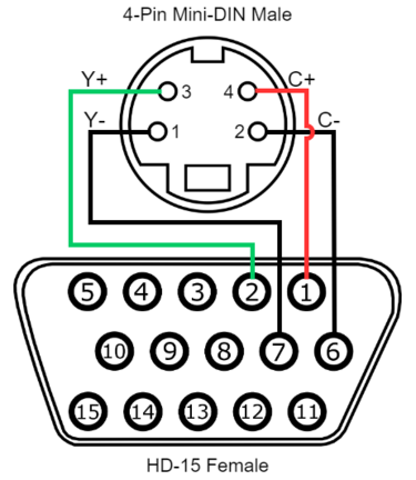 |
Signal | HD-15 (Female) | 4-Pin Mini Din (Male) |
| Luma (Y) Signal | 2 (Green) | 3 | |
| Luma (Y) Ground | 7 (Green Ground) | 1 | |
| Chroma (C) Signal | 1 (Red) | 4 | |
| Chroma (C) Ground | 6 (Red Ground) | 2 | |
3.5mm TRS Audio
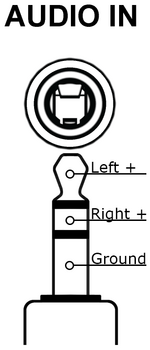 |
The RetroTINK allows for audio through a 3.5mm TRS input. This accepts stereo analog audio. By default, this is associated with the HD-15 port, as that port does not accept audio signals. |
Optical Audio
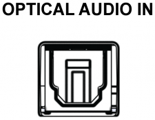 |
The RetroTINK offers a discrete optical audio TOSLINK input. This input can accept 2-channel LPCM and compressed surround sound. |
Alternate Audio Inputs
The RetroTINK allows you to reassign audio inputs from their default video source. Go to Advanced Settings, and select "Audio Input" under the "Acquisition" section. The "Input Override" option under "Source" allows the audio for the current input video input to be taken from a different audio source. The only exception is that it is not possible to assign HDMI® audio to a non-HDMI® video source. The reverse, however, is possible.
- This menu also has the Input Swap option, letting you swap the audio input channels (handy for some third-party Saturn cables), or derive mono audio using the left or right channels (useful for single-channel systems like the NES).
| Picture | Name | Description |
|---|---|---|
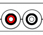 |
RCA (Rear) | The leftmost two RCA inputs in the rear. White and Red, |
|
HD-15 | The 3.5mm TRS input in the rear. |
|
SCART | The SCART input on the side. Audio is fed in through pins 2 and 6. |
|
Front | The red and white RCA inputs in the front of the unit. |
|
S/PDIF | Optical audio fed through a TOSLINK input. |
HDMI® Output
The RetroTINK only outputs via the HDMI® Out port. Note that the RetroTINK can not output video or audio through any other port.
The HDMI® Output menu allows you to set your output resolution, enable black frame insertion, change your color space output (colorimetry), and more. Here is a breakdown of the functions in this menu:
Output Resolutions
The following outputs are readily supported by the RetroTINK, and are provided in Output Resolution options in the HDMI® Output menu. Which resolutions available by pushing their respective button on the remote are also noted. If you are unsure which resolution to use, use the buttons on the remote to quickly try them.
| Resolution | Description | Remote Button? |
|---|---|---|
| 4K60 | Default resolution and framerate for 4k displays, aka 3840x2160p.
Default Resolution for the RT4K Not available on 6X models |
Yes |
| 4K50 | Intended for PAL games and 24Hz content.
Not available on 6X models |
No |
| 1080p60 | Default resolution for 1080p displays.
Default resolution for 6X models |
Yes |
| 1080p50 | Intended for PAL games, and 24Hz content | No |
| 1440p60 | Default resolution and framerate for 1440p monitors, aka 2560x1440p. | Yes |
| 1440p50 | Intended for PAL games and 24Hz content | No |
| 1080p100 | Intended for PAL games and 24Hz content with BFI | No |
| 1440p100 | Intended for PAL games and 24Hz content with BFI | No |
| 1080p120 | Intended for NTSC content with BFI | No |
| 1440p120 | Intended for NTSC content with BFI | No |
| 480p60 | Minimum suggested output resolution for modern displays, aka 720x480p.
Pressing the Reset button on the back of the unit activates this resolution. |
Yes |
| Custom 1 | Custom resolutions loaded from custom[1-4].txt on the SD card.
See Custom Modelines for further explanation |
Yes |
| Custom 2 | Yes | |
| Custom 3 | Yes | |
| Custom 4 | Yes |
| As of firmware version 1.5.1 the RetroTINK supports interlaced output resolutions, such as 480i, 576i, or 1080i. Interlaced output is intended to turn a progressive input into an interlaced output with the same resolution, or act as a passthrough. E.g. 1080p/i -> 1080i or 480p/i -> 480i. |
HDR
HDR is a way for the RetroTINK to output a much more luminous picture for TVs that support it. HDR is intended for use with either Black Frame Insertion or Scanlines and Masks, as it helps compensate for the darkened image.
- Two options are available: "HDR10 [8-bit]" and "HLG [8-bit]". These are different standards of HDR, but should provide equivalent results.
- You can adjust the brightness of HDR by going to Advanced Settings > Color Correction, then adjusting the "SMPTE 2084 PQ" value. This is useful if you want to play in HDR without scanlines, so that light tones are perceptible instead of being overly bright. If you're dead-set on doing that, 520.8 nits is a good level to use.
- As of firmware version 1.5.4, the RetroTINK can automatically pass through HDR10 and HLG signals. When an HDR signal is detected in the HDMI input, it cannot be turned off; this must be done via the system outputting HDR to the RT4K.
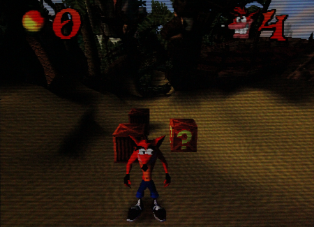
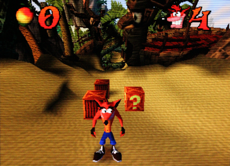
The table below shows two photos of an LG-CX displaying the RT4K using the "PVM 600 TVL" profile, under the HDR CRT Simulation folder. It's impossible to communicate the luminance of HDR in SDR, so here the camera had its exposure set for the HDR photo first, demonstrating the luminance gain compared to the SDR photo.
| PVM 600 TVL scanlines - SDR | PVM 600 TVL scanlines - HDR |
|---|---|
 |
 |
| HDR is intended for use with Scanlines, masks, and BFI. If you are not using any of these features, it is best to turn HDR off. If your picture is too dark, consider adjusting your input [ADC adjustments], tweaking your output color space with your colorimetry (see below), or making color corrections [CSC Color Correction] |
Colorimetry
HDMI® Output Colorimetry specifies the color space of the HDMI® output. By default, the Auto setting will select Rec. 709, and toggle to Rec. 2100 when HDR is enabled. You may wish to manually set output to Rec. 2020 (without HDR enabled), Adobe RGB or DCI-P3 if your display supports a wider color gamut. This may improve the image quality/accuracy when using the settings in the Color Correction menu.
RGB Range
This menu allows you to determine the HDMI®'s RGB Range of the RetroTINK's output. There are two options: Full Range (intended for computer monitors) and Limited Range (intended for televisions). Neither setting is perceptibly better than the other.
| You must make sure your RetroTINK and display match ranges. Almost all modern displays and monitors are able to use both, which makes it especially important to make sure they all match. If set incorrectly, the picture can appear either too dark or washed out. |
Here are some other considerations when setting up the RGB Range:
- Some devices will refer to these with different terms. For example, OBS refers to it as "Color Range", while LG televisions call it "Black Level" that can be set to "Low" or "High".
- if you're recording via capture software, you should also check that its range is set correctly.
- If the picture still looks incorrect, check Advanced Settings -> HDMI Receiver -> Input Range and make sure it's set to either "Auto" or matches the console's output range.
Sync Lock
Sync Lock controls how the RetroTINK synchronizes the output frame rate with the input frame rate, and handles these input changes.
Older video game consoles didn't always have perfect video timings, and while CRTs typically had no problems working with them, these "imprecise" consoles can sometimes have trouble working with modern TVs and capture devices that conform to a more rigid standard. Some games, such as Silent Hill or Chrono Cross on the PlayStation 1, will alternate between 240p or 480i video modes if you are in-game or in the items / pause menu, respectively. On many displays, upscalers and capture devices, this will create a long delay and a "no input detected" screen for several seconds while the device reorients to the new video mode. The issue of a device taking a gameplay-harming amount of time to change between video modes has been colloquially called the "Chrono Cross" problem. How the RetroTINK handles all of this can be chosen in the Sync Lock section.
- Triple Buffer - Operates the output independently from the input, which results in a stable output signal even if the input signal glitches or changes. However, this comes at the cost of a variable lag, usually between a fraction of a frame to a fraction of a frame plus one whole frame. On occasion, you will see judder when frames need to be dropped or repeated in order to maintain sync. Use this setting for video capture.
- Gen Lock - This is the recommended mode as long as your display is compatible with the source's refresh rate. Gen Lock loosely couples the output frame rate with the input frame rate. After a few seconds, the output frame rate will lock with the input frame rate and achieve minimum lag without screen judder. If Gen Lock is giving your equipment trouble, try enabling VRR if the display supports it.
- Frame Lock - Tightly couples the input and output frame rates. Any change in the input frame rate will cause a disruption in the output signal and a hard re-synchronization.
- TBC - Similar to Gen Lock but has better handling for sync glitches. The frame rate converges slower than with Gen Lock.
- Adaptive Triple Buffer (A. Buffer) - Similar to Triple Buffer mode, but will automatically switch to 50 Hz output for 50 Hz input signals. Useful for PAL consoles that switch between 50 Hz and 60 Hz. To use this mode, select a 60 Hz output mode. 50 Hz output from this mode may have lower TV compatibility than manually switching between the built in 60 Hz and 50 Hz modelines.
| Note that the Gen Lock and Frame Lock Sync Lock selections will display "Gen Out of Range!" and "Fr. Out of Range!" respectively when the video input frame rate is too far from the selected output to operate. An input more than 19% faster than the selected output frame rate or 30% slower than the selected output frame rate will trigger this error. When Gen and Frame Lock sync is out of range, the RetroTINK buffer will fall back to the triple buffer Sync Lock method, using the frame rate specified in the selected modeline. |
| Triple Buffer, Gen Lock, and Frame Lock are decreasingly compatible, respectively. If you have trouble with Gen Lock or Frame Lock modes, consider going back to Triple Buffer by pressing the BUF button on the remote. |
| Profiles normally default to Triple Buffer for maximum compatibility. Feel free to test your equipment: switch to Gen Lock by pressing the GEN button on the remote and saving your profile to default to Gen Lock in the future. |
VRR (Variable Refresh Rate)
The RetroTINK can flag its output as VRR. While the RetroTINK itself never outputs variable frame rates, settings this flag may be useful to force the display to accept a broader range of refresh rates, including if you're using Gen Lock. It is also useful on some displays to prevent re-buffering and other frame rate changes, which will interfere with the RetroTINK's BFI generator. Lastly, some TVs activate a low-lag mode if they detect the VRR flag, which will improve the gameplay experience.
Deep Color
This option changes the bit color depth of the RetroTINK from 8 bits (Off) to 10-bits (On), increasing the number of colors in the picture. This can be useful if you've used any setting that adjusts the color of the picture. Note that enabling Deep Color will prompt an on-screen confirmation box requiring the user to select "OK" before enabling the feature.
| Engaging Deep Color may cause issues with some equipment like TVs or capture cards, since enabling it while using 4K60 output will exceed the HDMI 2.0 bandwidth spec. In this case, your options are to either disable Deep Color, or use a lower output resolution. PAL systems may have better luck if the 4K50 option is chosen instead, so long as HDR is disabled. |
BFI Control
Gives you quick access to the Strobe and Blur functions of Black Frame Insertion. For explanations on what these do, head to the Black Frame Insertion (BFI) section.
Audio Output
Surround Sound
The RetroTINK outputs up to 8 channels LPCM via HDMI®. As of Firmware 1.4.2, and per previous testing all 8 channels are output simultaneously but the channels are correctly routed, so if your receiver reports 7.1 but is only a 5.1 receiver, you should still have correct function from the RetroTINK.
The RetroTINK also passes through Dolby Surround® and all previous iterations of Dolby Surround®. This encodes surround sound in stereo signals so it is entirely up to your receiver to decode surround from this signal.
Profiles
| All options should be stored in a single profile. If you load a new profile, consider all previously changed settings lost if you did not save these settings to a new profile. This includes, but is not limited to, inputs, output resolutions, and scanline settings. Consider saving settings for profiles before switching between them for comparison. |
The Profiles section handles all of the profiles provided on the SD card, as well as any you've put there yourself. Profiles allow you to save your settings to load later. This is where you'll find CRT presets, since they're just saved profiles.
- For a list of Profiles provided on the SD card by default, head to the Profiles breakout page.
- For a collection of Profiles made by the community not provided on the SD card by default, head to the Community Profiles section.
Load Profile
- Load From File - Selecting this will bring up a menu where you can navigate through the "profile" folder on the SD card to load up a specific profile.
- Load Default - Loads the Default Profile. The Default Profile can never be deleted or overwritten.
- Auto Load DV1 - Will automatically load a DV1 profile, based on the detected DV1-compatible MiSTer core or console HDMI mod. Requires the RT4K to be on the HDMI input, the name of the profile to match the core name (
core-name.rt4), and for the profile to be located in the DV1 folder. The core name can be found at the bottom of the RT4K menu (Mode: MiSTer 240p (core-name)), as well as in the resolution change popup in the top right corner. Please note: The MiSTer's own OSD menu also shows the core name on the left side, but for longer names, only the first 14 characters are sent to the RT4K.- Example:
sdcard\profile\dv1\batrideru.rt4
- Example:
- Auto Load SVS - Will automatically load an SVS profile, when a serial command from a Scalable Video Switch or compatible device is received. SVS profile files are placed in the SVS folder and must be named 'S<input number>_<user defined>.rt4'. When the SVS first detects all inputs are off, it will load the profile 'S0_<user defined>.rt4'. If there's more than one profile that fits the pattern, the first match is used.
- Profile 1 refers to the module closest to the control unit, profile 2 referes to the second closest module to the control module, etc.
- Example:
sdcard\profile\svs\S2_SNES.rt4
The arrangement of profiles in the Load From File menu matches the internal file structure of the "profile" folder on the SD card. This means that you can alter the folder structure to your liking if you don't prefer how they're laid out by default.
| Auto Load SVS requires a VGA cable that has pins 12 and 15 connected. |
The following features were added in experimental firmware 1.24.0 and work regardless of profile settings. These do not apply to profiles that use the DV1 and SVS options to load profiles. These will help with A/B comparisons
- Keep Cur. Input: This setting forces the RetroTINK to stay on the currently selected input. A profile may typically be made with one input in mind, but CRT profiles may be used with multiple inputs. This option helps switch between profiles without the extra steps of selecting an input.
- Keep Cur. Res: This option is designed to keep resolution continuity for users with non 4K displays. See the descriptions of the options below:
- Off: The RetroTINK keeps its original settings and uses the resolution selected within the profile
- On: The RT4K overrides the profile's selected resolution with the current output resolution.
- On + Auto Scale: On top of overriding the profile's resolution selection, the RetroTINK overrides the profile's Scaling Mode option.
- This option attempts to translate the scaling factors from the profile's settings to settings that would work well with the currently selected output resolution.
Save Profile
- Save Current - Overwrites the currently-loaded profile with the current settings. If selected while using the Default Profile, this will work like "Save As New" instead.
- Save As New - Saves the current profile as a new file named "New Profile X", where X is an ascending number. This will be located in the root "profile" folder on the SD card, and can be renamed using a PC.
Assign Profile
This section of the menu allows you to assign one of the twelve number buttons at the top of the remote to a specific profile, using the same SD card navigation menu as the "Load From File" function.
Additionally, this is where you can assign a profile to be loaded up when the RetroTINK is Powered Up. This is not the Default Profile, which can never be changed.
Assigned profiles can be cleared by highlighting the button you want to edit and pushing ◁ (Left) on the remote.
Nested Profile Settings
| Nested Profile Diagram | ||
|---|---|---|
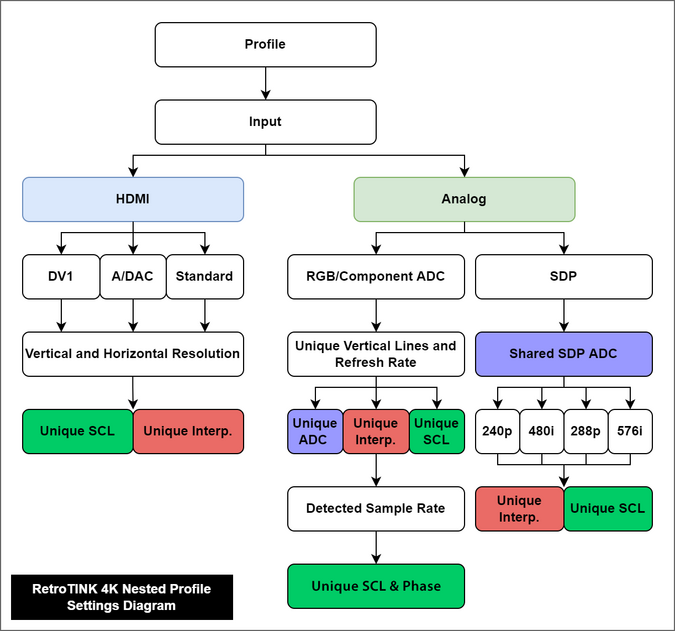 |
The RetroTINK profile system has deeper functionality than might initially appear. By meeting certain conditions, the "ADC" (RGB/Component ADC), "SCL" (Scaling and Crop) and "Interpolation" (Processing/Effects Setup - Interpolation) can have multiple, unique entries.
The criteria that can trigger nested settings include:
Please refer to the Nested Profile Settings Diagram for a visual aid to what conditions will trigger unique, nested settings. Unique Settings
| |
| Note that every setting, included nested settings, are able to be saved within the profile (".rt4" file). The only exception are the Power Control settings in the OSD/Firmware menu. The Power Control settings apply globally and are saved to the root of the SD card. |
Scaling and Cropping
The Scaling / Crop Setup menu is where you can crop and resize the image. Unlike the RetroTINK-5X, by default the RetroTINK-4K/6X models size and position the image based on the cropping, but this can be overridden with the Scaling Mode setting.
Input Crop
The RetroTINK has robust controls to adjust size, positioning and cropping:
- "Top Trim" and "Bottom Trim" will effectively scale the image up and down in most Scaling Modes.
- To more easily see the edges of the Top and Bottom Trims, set the Scaling Mode to "Auto Fill Integer".
- "Left Trim" and "Right Trim" will adjust the centering of the image, as the RetroTINK automatically centers the image based on these settings.
- To shift the image left and right, increase the Left or Right trim to push the image in the opposite direction.
Vertical Pre-Scale
The RetroTINK features the ability to "Pre-Scale" video content, or discard scanlines, at a fractional increment of the source input. Discarding vertical lines results in a loss of vertical resolution. This loss can be useful under certain circumstances, such as creating more accurate scanline rendering for 240p visual content output from consoles that run at higher resolutions (such as the Dreamcast or Wii).
RoTATE (4K Pro)
| The RoTATE feature is exclusive to the RT4K Pro model, and is unavailable on any other model |
RoTATE (pronounced "roh-tah-tay") is a special feature within the RetroTINK-4K Pro model to rotate the image 90 degrees clockwise (right) or counterclockwise (left). This is especially useful for games that may only display their image horizontally, such as many arcade shooters.
| RoTATE Example | ||
|---|---|---|
| Standard Output | 90 Degrees Right | 90 Degrees Left |
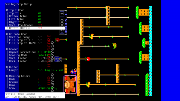 |
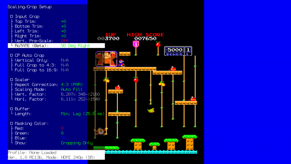 |
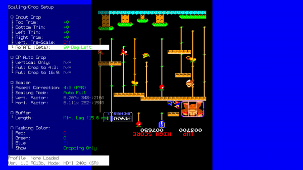 |
The RoTATE mode will only work if the samples per line of your video source is lower than 1024 samples per line (visible in the RGB/Component ADC menu).
- Because the video of Composite and S-Video is locked to 858 samples per line, no additional tweaking is required when using these input sources.
- Further, RoTATE mode will only work with 240p, 288p or 360p resolutions. This is important for titles that mix them with 480i.
If you're using RGB or YPbPr input, visit the RGB/Component ADC section of this page for information on ADC and decimation settings to meet the 1024 samples per line requirement. Similar limits apply when using HDMI® sources: use the Input Decimation settings in the "HDMI® Receiver" menu if the horizontal samples exceed 1024 (for example, MiSTer cores that use pixel repetition).
Auto Crop
The RetroTINK can automatically crop and set aspect ratio for an input if it is fed a sufficient game screen. This feature works with RGB,Component and HDMI™ sources. Auto Crop looks for the black edges of a game image and crops to them, so use a picture that clearly shows the edges of the video for best results.
| Screens that have any dark edges, as well as letterboxed, pillar-boxed, and window-boxed screens, are not recommended as they will fool the Auto Crop into thinking those are the edges of the image, resulting in an incorrect crop. |
| Name | Remote Button | Effect |
|---|---|---|
| Vertical Only | AUX 1 | Automatically adjusts "Top Trim" and "Bottom Trim" to the top and bottom of the game image. Does not adjust Left Trim or Right Trim, and does not change Aspect Correction. |
| Full Crop to 4:3 | AUX 2 | Automatically adjusts Left, Right, Top, and Bottom Trim to the image, and changes Aspect Correction to "4:3 (PAR)" |
| Full Crop to 16:9 | AUX 3 | Automatically adjusts Left, Right, Top, and Bottom Trim to the image, and changes Aspect Correction to "16:9 (PAR)" |
Scaler
The Scaler section in the RetroTINK is where you'll find the tools that allow you to manipulate the geometry of the image.
Aspect Correction
The Aspect Correction setting chooses the Pixel Aspect Ratio, or "PAR", of the image. This is important because it needs to match the aspect ratio of the display the game is expecting to be seen on, referred to as the Display Aspect Ratio, or "DAR".
| The Aspect Correction controls are only available when the current Input (analog or HDMI®) is a resolution with a variable PAR factor, such as 240p, 288p, 480i/p, and 576i/p. Most other resolutions will lock the Aspect Correction setting to their expected PAR, no matter the input. For example, 720p over the PS3's Component cables will lock Aspect Correction to "1:1 (Sq. Pixel)", while 480p over PS3's HDMI® cables will let you choose yourself.
|
The options that are available are:
| Pixel Aspect Ratio | Description | Display Aspect Ratio Use-Case |
|---|---|---|
| 4:3 (PAR) | Uses the common 4:3 Pixel Aspect Ratio, displaying the pixels slightly wider or narrower than squares depending on the input resolution. | Pre-HDMI® video game consoles, which expect to be displayed on the 4:3 DAR of CRT televisions. |
| 16:9 (PAR) | Uses the 16:9 Pixel Aspect Ratio, displaying the pixels even wider than 4:3 (PAR). | Pre-HDMI® games and systems that offer widescreen modes, such as with the PS2 and the Wii. |
| 1:1 (Sq. Pixel) | Uses the 1:1 Pixel Aspect Ratio, displaying the pixels as perfect squares. | Games and consoles that expect a 1:1 PAR but still output a sub-HD signal, such as PSP, and Game Boy games via the Super Game Boy or Game Boy Player. |
If you're using a device that can use more than one Pixel Aspect Ratio, it's important that you set said device to correctly dovetail with the RetroTINK, so that the game will be shown correctly once it gets to your display.
Scaling Mode
Scaling Mode allows you to select automatic scaling modes or change aspect ratio constraints on manual scaling:
- Auto Fill - Fills the screen based on the selected Aspect Correction aspect ratio.
- Proportional - Allows the Vertical Factor to be adjusted while automatically adjusting the Horizontal Factor to keep the aspect ratio selected in Aspect Correction.
- Free-Form - Untethers the Vertical Factor and Horizontal Factor to allow values outside of the Aspect Correction setting. This setting lets you use the Vert. Factor and Hori. Factor settings to freely transform the image, like on the RetroTINK-5X.
- Auto Fill Integer - Scales the Vertical Factor and Horizontal Factor to the highest possible integer value without exceeding the screen boundaries, while also respecting the ratio selected in Aspect Correction. We highly recommend using the cropping tools to ensure the picture can be as large as possible while using this scaling mode.
Scaling Factors (Transform Tools)
The Horizontal Factor and Vertical Factor settings allow you to stretch and transform the image, either horizontally or vertically. Each factor diplays the multiplier value, the input resolution, and output resolution respectively.
Which of these are available depends on what option the Scaling Mode is set to. Proportional unlocks the Vert. Factor, while Free-Form unlocks both Vert. and Hori. Factors.
The function can be expressed as a simple formula: [Input Resolution] X [Multiplier] = [Output Resolution].
| Horizontal and Vertical Factor Example | |||
|---|---|---|---|
| Axis | Multiplier | Input Res. | Output Res. |
| Vert. Factor | 9.000 | 240 | 2160 |
| Hori. Factor | 2.045 | 1440 | 2945 |
Buffer Length
The RetroTINK allows users to set how much video to buffer before outputting to your screen. The buffer, in conjunction with the Sync Lock mode, are the main determining factors for overall latency.
- Min. Lag - Sets the buffer to only store to bare minimum number of video lines. This option provides the lowest latency.
- 1/2 Frame - Always buffers half a frame.
- 1 Frame - Always buffers a full frame.
Min. Lag is typically compatible, but if you encounter an edge case with screen tearing, try setting this to "1/2 Frame" or "1 Frame".
| Certain movie modes, such as Inverse Telecine, will automatically force the RetroTINK-4K Pro to buffer a full frame. |
Blank Resolution Change
Blank Resolution Change will add a black frame between resolution changes to mask image glitching. This can be helpful to smooth out transitions in games that commonly switch between 480i and 240p. Famous examples include Chrono Cross and Silent Hill on PS1. Blank Resolution change can be set to "On" or "Off".
Masking Color
The masking colour settings allow you to adjust the colour of the mask that displays in the Scaling/Crop menu. By default, the values a 0 Red, 0 Green and 31 Blue. You can also change whether the masking colour is displayed in the cropping menu only, or always (even when the RetroTINK menu isn't displayed).
Processing and Effects
The Processing / Effects Setup menu is where you can adjust the pixel interpolation, as well as add Scanlines and CRT Masks.
Where are the Scanline Presets?
If you're a regular user of the RetroTINK-5X, you may be surprised to enter this menu and find that there's no Presets available to choose from. This is because they are stored as Profiles on the SD card.
- To load an included CRT Preset, head to the main menu, then go Profiles > Load from File > CRT Simulation, then pick one you want to use.
The "bundling" of CRT Presets as Profiles may seem odd to users of the RetroTINK-5X (where CRT Presets could easily be applied to optimal sampling profiles), however this shouldn't have much impact on the final result. CRT displays are inherently a bit blurry as part of their aesthetic (even PVMs and BVMs), so generic sampling is perfectly acceptable to use for them. If you're using a digital source and decimating it (like Nintendo Switch Online or an HDMI® modded system), you may want to simulate the blur using the Horizontal Interpolation Kernel, and / or the Horizontal Blur function.
The only exception to the above is when you're using the LCD scanlines, as the thin lines dividing each pixel won't appear correctly without scaling the image up by a flat number (such as 4.000x or 5.000x).
RetroTINK-5X Equivalent Scanlines
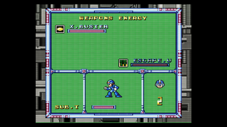
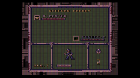
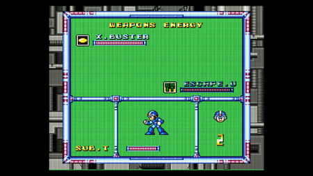
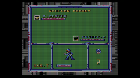
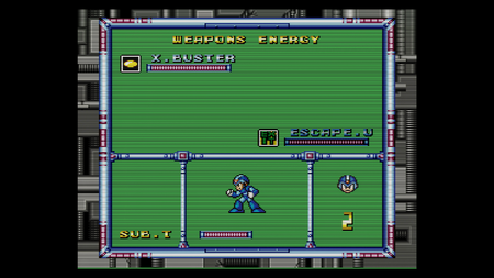
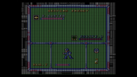
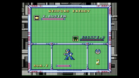
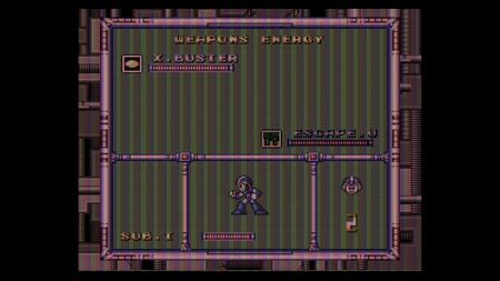
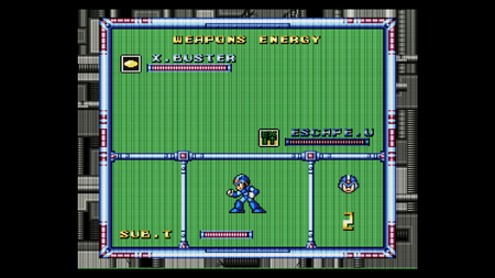
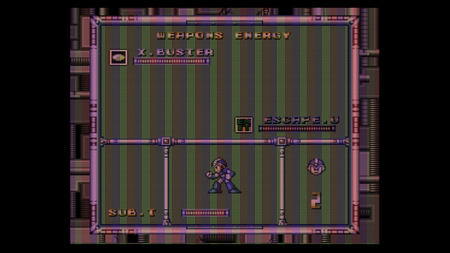
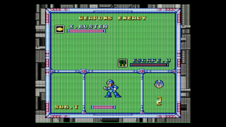
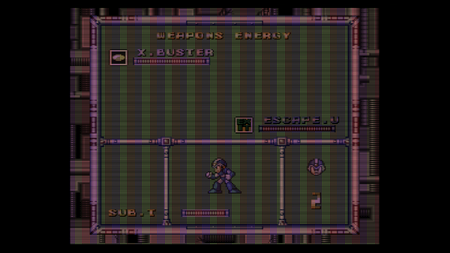
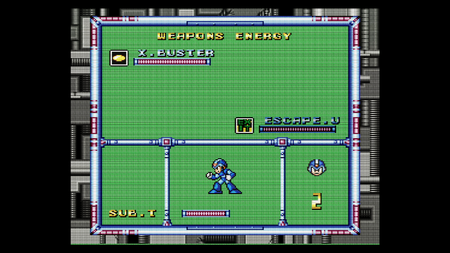
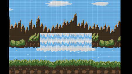
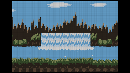
The following profiles are analogous to similar presets on the RetroTINK-5X, these can be found in the \profile\_CRT Emulation\Basic HDR CRT\ folder on the RT4K SD Card. The 5X Screenshots were generated at 1440p on the 5X and then scaled to 4K to approximate the way they may be seen on a 4K display, for easily comparing to the same scene generated by the RetroTINK-4K Pro in 4K on the same display. We strongly encourage you to click on the image and zoom in to see the shape and color of the effects.
| If you liked this preset on the 5x | Then You should try this profile on the RT4K |
|---|---|
 |
 |
 |
 |
 |
 |
 |
 |
 |
 |
 |
 |
 |
Pending Equivalent Profile |
 |
 |
RetroTINK-4K Pro vs RetroTINK-4K CE
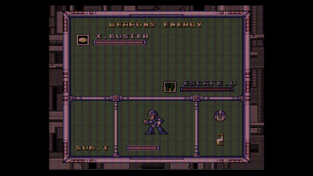
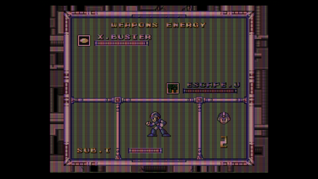
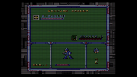
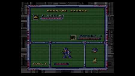
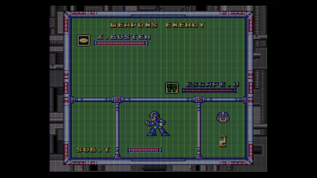
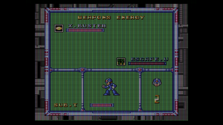
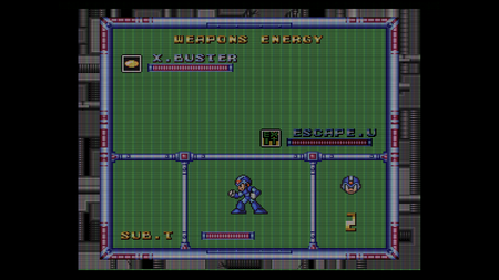
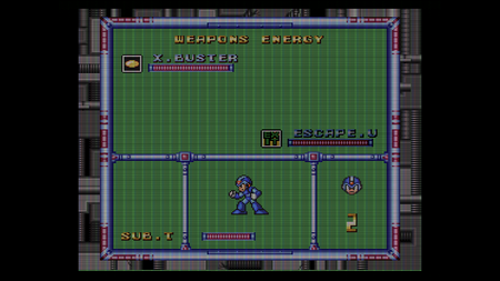
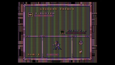
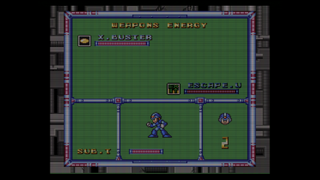
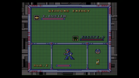
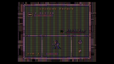
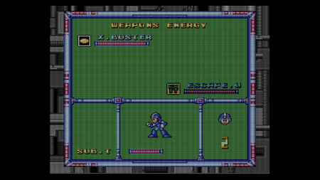
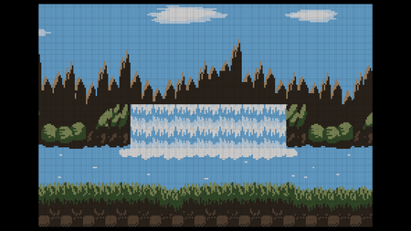
See below for comparisons of major CRT Effect profiles for both the Pro and CE models of the RetroTINK-4K. These profiles are only different if the profile makes use of the IIR LPF feature exclusive to the Pro model.
| Pro | CE | Pro | CE | Pro | CE | Pro | CE | |||
|---|---|---|---|---|---|---|---|---|---|---|
| Hi-Res Slot Mask | JVC D-Series-D200 | AG Coarse | Slot Coarse | |||||||
|
 |
 |
 |
|
 |
 |
 | |||
| BVM 1000 | JVC TM-H150CG | AG Dense | Slot Dense | |||||||
|
 |
 |
 |
 |
 |
 |
 | |||
| PVM-600 | JVC TM-H1950CG | AG RYB | Slot Medium | |||||||
|
 |
 |
 |
 |
 |
 |
 | |||
| Consumer Trinitron | Sony KV-FV310 | AG YMC | Triad Coarse | |||||||
|
 |
 |
 |
 |
 |
 |
 | |||
| Consumer Slot Mask | Sony PVM 20L5 | Mono Dense | Triad Dense | |||||||
|
 |
 |
 |
 |
 |
 |
 | |||
| LCD Mono | Toshiba AF44 | Mono Medium | ||||||||
|
 |
 |
 |
 |
 | |||||