 | The steps on this page are considered risky for your console, as there is a chance you can brick it. Please have someone else mod your console if you are not experienced in soldering! |
| Sellers/installers that advertise an "improved RGH3" likely use voltage regulators or MOSFETs. While not dangerous, the improvement is nonexistant. Please avoid such installers and always ask for install pictures before doing business. |
 | Phat consoles tend to be more stubborn with RGH3, and may have inconsistant booting behavior. It is recommended to use RGH 1.2 on a phat system, as it will be more likely to be stable. |
RGH 3 is a modern method of the Reset Glitch Hack that uses the SMC in the Xbox 360's southbridge instead of an external glitch chip in order to boot unsigned code.
MrMario2011 has video guides for RGH 3 on Falcon/Jasper[1], Trinity[2], and Corona [3] motherboards respectively. The guides from Larvs on Xbox 360 Hub[4] and BeefyDJ on Se7enSins[5] are also great resources for RGH 3 tutorials.
Issues with Falcon/Jasper/Tonasket "phat" models
RGH 3 works best on S and E models. Although RGH 3 can be installed on Falcon and Jasper boards, it should NEVER be treated as a "one-and-done" solution. At its best, RGH 3 can boot phats almost as fast as RGH1.2 (less than 8 seconds) but more often than not will be at its average (10-20 seconds) or even at its worst (20+ seconds and even minutes).
15432's writeup on how RGH 3 works, as well as Octal450's analysis, help explain why RGH 3 has issues on phats. A full list of reasons is:
- PLL slowdown on phats isn't precise enough. The S/E's Vejle XCGPU offers a 640x PLL slowdown when asserted. In contrast, the Loki XCPU on Falcon/Jasper/Tonasket only has a 128x PLL slowdown. This ties into the second problem:
- The SMC is too slow for the job. RGH 3 is handled by the SMC (System Management Controller) in the Southbridge (XSB, PSB or KSB chip). While the Xbox 360's CPU is a modern PowerPC that can execute one instruction per clock cycle, the SMC is based on the ancient Intel 8051, which can take many clock cycles to execute one instruction (12 cycles at best). While RGH 3 combines PLL slowdown (as in RGH1.2) and I2C slowdown (as in RGH2), the SMC still can't time the reset pulse correctly. And the reset pulse must be timed precisely (typically between 100-200 nanoseconds), otherwise the CPU will either fail to glitch or crash early during the boot process. 15432 explains that he experimented with overclocking the SMC to compensate for this, but again, it can't fully overcome the 8051's technical limitations. Meanwhile, glitch chips based around FPGA/CPLD programmable logic devices, or even modern microcontrollers, can time their reset pulses to 1 or 0.5 cycle precision, making them far more precise than the SMC will ever be.
- The Loki CPU is based on 1.1V logic, while the SMC is based on 3.3V logic. This affects the POST pin signal and is why the diode/resistor is used. In short, any CPU or microcontroller needs to see a voltage between certain ranges to successfully register it as a digital 1 or a 0. The POST pin will be at 0 volts to signal a 0, which the SMC can pick up on, but at 1.1 volts, a logical 1 from the POST signal might not successfully register in time, if at all. This will either throw off RGH 3 timings (which, as mentioned, need to be precise), or cause the SMC to hang until the system watchdogs (times out and resets to standby mode).
- RGH 3 is harder to tune. With RGH 1.2 and even EXT_CLK, there's a wide choice of timings that can be used. On RGH 3, there are only two possible timings for phats: 27 MHz and 10 MHz. These only set the base CPU clock (normally 100 MHz, which the CPU multiplies by 32 internally), and not the reset delay/reset glitch pulse width timings themselves (which is why those methods have so many timing files available). And it bears repeating that the SMC can't time anything too precisely, which limits the number of possible working timings.
- Jasper problems. RGH 1.2 can be uncooperative on Jasper/Tonkaset boards and those difficulties carry over into RGH 3. The typical Jasper issues with RGH 3 include slow boots and the console powering off immediately on startup.
- Combined PLL/I2C slowdown issues. RGH 3 relies on combined PLL and I2C slowdown, both of which must be toggled at the right times or else the CPU will crash. Some consoles may not play well with the combined slowdown and will consequently have a low success rate with RGH 3.
The tl;dr is: RGH 3 will never work as well on phats as it does on slims because reset glitching demands precise timings that phats can't really manage. In contrast, a properly done RGH 1.2 on a Phat will consistently boot in one glitch cycle. So, if you try RGH 3 on your phat and find it doesn't cooperate, your options are to either live with it, or convert the system to RGH1.2 if possible.
Regarding claims about improved RGH 3 on phats using voltage regulators
The most concise response that can be offered to these claims is "lol", or alternatively, "lmao".
- Fast/ultrafast diodes and MOSFETs can switch very fast because that's what they're designed to do. Voltage regulators are only designed to regulate a power source to a certain voltage, not to switch digital logic signals. The voltage regulator only succeeds in making glitching performance about the same or even worse than the usual diode/resistor combo.
- The PLL bypass control inside the CPU is almost certainly switched using a MOSFET, which is voltage-driven, rather than a bipolar transistor, which can turn on harder in response to a higher base current. So even if a higher current is provided to the PLL pin, the PLL circuitry will most likely use a fraction of what's available.
- Even if voltage regulators could switch a signal instantaneously, it wouldn't overcome the limitations of the SMC, which is slow and can't time its reset glitch pulses precisely.
Updated phat RGH 3 ECCs
15432 has released updating ECC files that include SMC overclocking mode on phats. They are available, with the source code, here.
These ECC files are included with J-Runner with Extras as of V3.4.0. To use the overclocked ECC, select "OC" in the MHz dropdown menu when building an RGH3 NAND image.
When doing the POST wire soldering for these new ECCs, utilize a 470 ohm resistor instead of a diode.
Equipment Needed
- A soldering iron, solder, flux, and Isopropyl alcohol with cotton swabs
- 28-30 AWG Wire (Solid core recommended)
- For PLL, a surface mount or through hole resistor resistor according to the requirements below; through-hole recommended for novices. (Required on Phat; Highly recommended on Trinity/Corona.)
- Falcon/Jasper/Tonasket: 22K Ohm (Red, Red, Orange, Gold; same value as on Matrix and other glitchers)
- DO NOT USE 10K FOR PHATS, those guides that say you can are outdated and wrong
- Trinity: 5K Ohm (Green, Black, Red, Gold)
- Corona: 1K Ohm (Brown, Black, Red, Gold)
- If using a surface mount resistor, it may be optimal to pick a size such as 0402 or smaller.
- Falcon/Jasper/Tonasket: 22K Ohm (Red, Red, Orange, Gold; same value as on Matrix and other glitchers)
- On POST for Falcon/Jasper/Tonasket, either a diode of your choice, such as a 1N4148, or a 470 ohm resistor.
- A 470 ohm resistor is recommended for use with the overclocked (OC) RGH3 files included with J-Runner 3.4.0 and later, whereas a diode such as the 1N4148 is recommended to use with the non-OC RGH3 ECCs.
- While it may not be optimal, the OC RGH3 files will work with a diode and the non-OC RGH3 files will work with a resistor
- It can either be through-hole or surface mount, though like with the other resistor, through-hole is preferred for novices.
- If using a surface mount resistor/diode, it may be optimal to pick a size such as 0402 or smaller.
- Wire insulation (Kapton tape, electrical tape, heat-shrink, etc.) if using a through hole resistor/diode
- A PC running Windows Vista or later
- J-Runner with Extras
- Any compatible NAND Programmer
Alternative resistor values
This is for more advanced installers.
When DBG_LED (SMC_PLL) is connected to the PLL bypass point via a resistor, it forms a voltage divider (combined with the CPU's internal pulldown) so that it can safely enable PLL bypass mode without damaging the CPU due to overvoltage.
The resistor value you choose should result in CPU_PLL_BYPASS receiving as close to the target voltage as possible. If the resistance is too high, it will not enable PLL bypass mode reliably. If the resistance is too low, you run the risk of damaging the CPU, the likelihood of which will increase the lower your resistor value is.
| Console | Vin | Vout | R2 | R1 values |
|---|---|---|---|---|
| Falcon/Jasper/Tonkaset | 3.3V | 1.1V | 10000 | 17500-23000 |
| Trinity (commonly used) | 3.3V | 1.8V | 5000 | 3700-5000 |
| Trinity (possibly safer) | 3.3V | 1.1V | 5000 | 8800-11500 |
| Corona (commonly used) | 1.8V | 1.8V | 5000 | 0-300 |
| Corona (possibly safer) | 1.8V | 1.1V | 5000 | 2500-4000 |
where:
- Vin is the southbridge's I/O voltage,
- Vout is the target voltage that should be fed to CPU_PLL_BYPASS,
- R2 is the default pulldown for the CPU_PLL_BYPASS pin, and
- R1 is the resistor value you could (not necessarily should) use.
Important notes:
- The Vejle CPU's PLL voltage is 1.8V; the Loki CPU's PLL voltage is 2.2V but it's not clear how well the PLL pin tolerates ~2.2V levels so everyone uses the CPU's I/O voltage of 1.1V.
- The R2 value for phats comes from the 10k pulldown resistor connected to the PLL point; the R2 value for slims was measured with a multimeter.
- It is possible that the common Trinity and Corona values are too low.
- If you use anything from this table for your install, do NOT start at the minimum R1 value as that is the absolute minimum. Instead, start around the middle and work your way down if you have problems.
- Once voltage increases above a certain threshold (i.e., you are feeding too much voltage to the PLL pin), it makes no difference how low your resistor value is as PLL bypass mode will always be triggered reliably.
Reading your NAND
Bad Update
With the Bad Update hypervisor exploit, it is entirely possible to get a NAND and CPU key dump from an Xbox 360 without even soldering to the console. This can end up saving a lot of time during the mod process, as you don't need to mess with soldering up a NAND flasher for a NAND dump & flash a XeLL image with an RGH installation to decrypt your NAND anymore. You can just do a NAND dump, decrypt it with the CPU key dumped with Simple 360 NAND flasher or XellLaunch, and directly create a Glitch2 RGH 3 NAND image that you can flash to the console.
You can use the homebrew apps for flashing the NAND as well, but this is strongly discouraged unless you already own a NAND flasher (comparison between the ones available shown below) that you can use to recover from a bad NAND image.
NAND Flashing Tool
There are a few different tools for reading your NAND chip: xFlasher 360, Nand-X, JR Programmer, Matrix USB NAND Flasher, PicoFlasher, or a LPT cable. Consider the pros and cons below and choose the method that’s right for you. An LPT cable is not recommended as it's extremely slow, requires more work than other options, and cannot be used to program glitch chips.
A guide on how to dump and write to a standard NAND can be found here.
4 GB Xbox 360 S/E SKUs made after mid 2011 use an MMC NAND (Corona) or eMMC chip (Waitsburg/Stingray/Winchester) These 4 GB consoles require that you use an xFlasher 360, PicoFlasher, Element18592's 4GB USB tool, or an SD card tool, as mentioned in the comparison chart.
A guide on how to dump and write to a 4 GB NAND can be found here.
| Device | Pros | Cons |
|---|---|---|
| xFlasher 360 |
|
|
| PicoFlasher |
|
|
| 4GB USB Tool |
|
|
| SD Card Tool (any brand) |
|
|
| Nand-X |
|
|
| Matrix USB NAND Flasher |
|
|
| LPT Cable |
|
|
Corona Specific Instructions
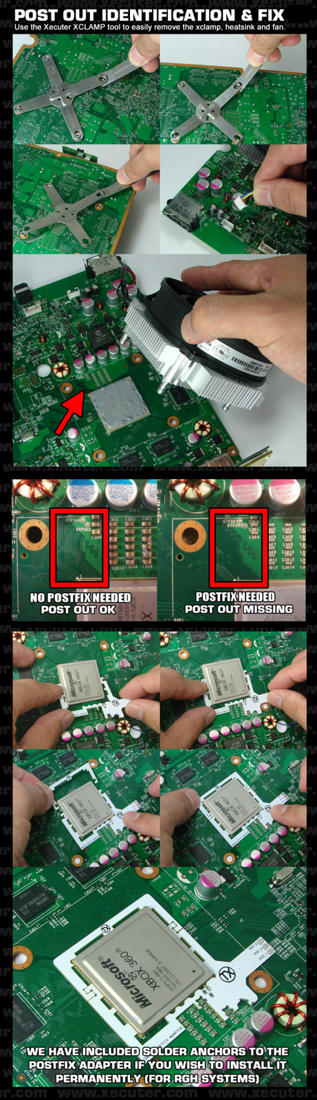
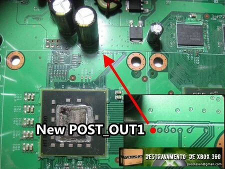
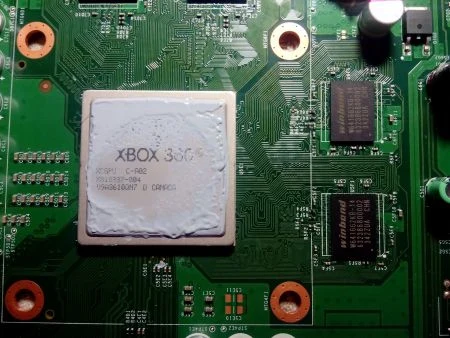
On later revisions of Corona based motherboards (named Waitsburg and Stingray for Xbox 360 S and E respectively), the trace connecting the CPU's POST to the POST pad on the bottom of the motherboard has been removed, so you need to use a postfix adapter to be able to attach a pogo pin to the POST connection underneath the CPU, allowing for CPU POST output once again. You can use the following image to determine if you need the adapter or not by removing the heatsink.
You can also identify if you have a Waitsburg motherboard from a Corona by looking for the part number of X862605 on the bottom left of the PCB. Generally, Xbox 360 S consoles manufactured in late 2011 and 2012 will be Waitsburgs and need postfix adapters for RGH. Every Stingray will also need a postfix adapter with RGH.
RGH 3 Wiring & Diagrams
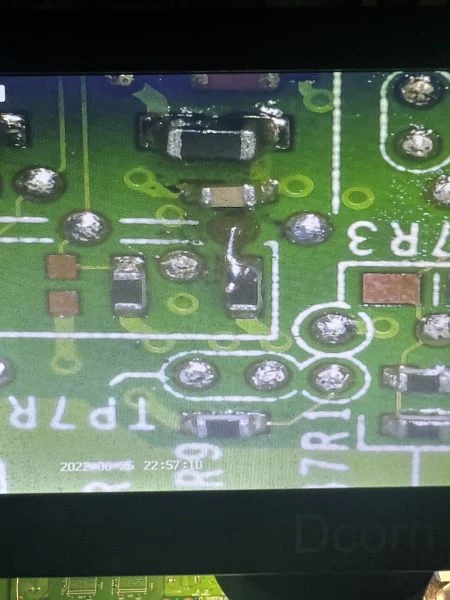
Xbox 360 "Phat" (Falcon/Jasper/Tonasket)
On Falcon/Jasper/Tonasket motherboards, you can place a diode or 470 ohm resistor on the wire that connects POST and SMC_POST. While it could be skipped, it is more likely the console's boot times will be more unstable or inconstant without it.
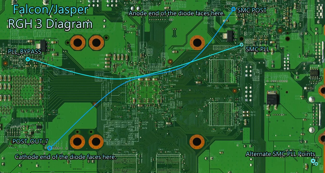
If you are using a diode, its cathode end (the side with a black band) connects to CPU POST, whereas its anode end connects to SMC_POST. Make sure the polarity is correct. Luckily, if you are using a resistor, you don't have to worry about polarity.
Make sure there is an in-line 22K resistor on PLL wire. It is not recommended whatsoever to use RGH 3 on Falcon or Jasper/Tonasket without the suggested resistor.
When using a through hole component, it is recommended to solder it inline the wire instead of soldering it directly to a pad. The wires will be less stiff than the component's legs, causing less strain to the joint if it moves around. Make sure the PLL wire is not nearby any high noise areas, like capacitors or coils.
Diagram
Alternate Diagram
Uses SMC_PLL on the top of the motherboard.
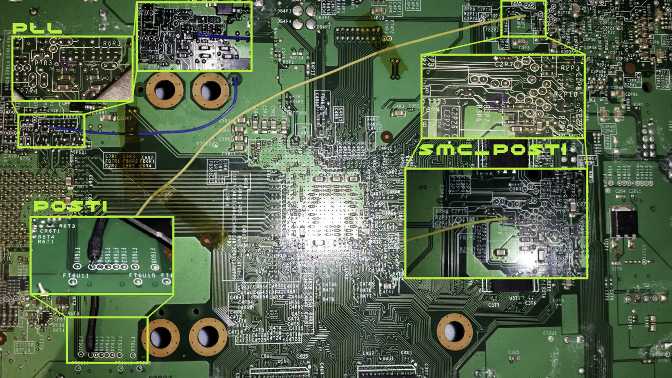
Alternate Diagram #2
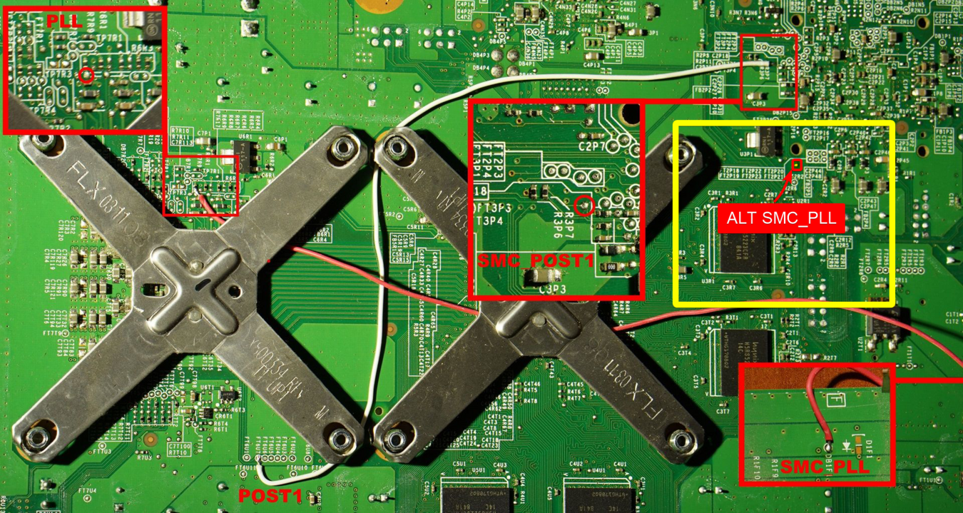
Alternate Example
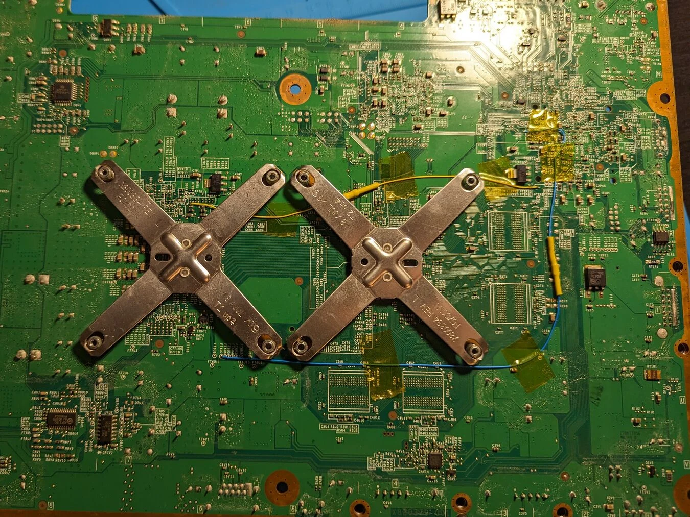
Close-Up Solder Points
CPU PLL
- Bottom
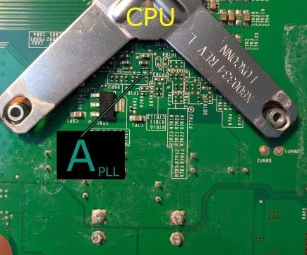
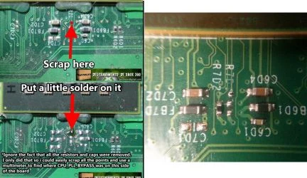
- Top (Requires Scraping)
CPU POST
- Bottom
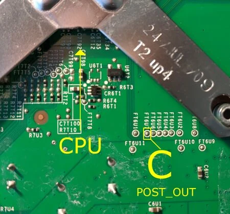
- Top (Requires Scraping)
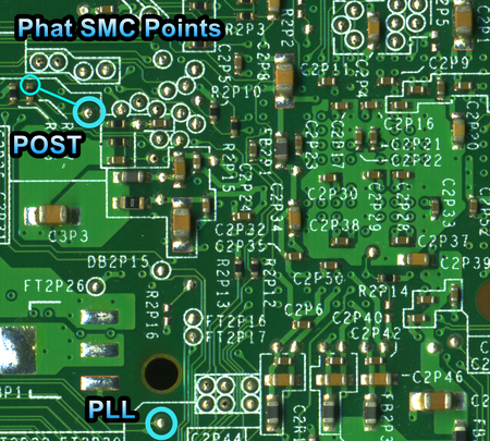
- GPU_RST_DONE & DBG_LED (used for SMC_POST & SMC_PLL) (Bottom)
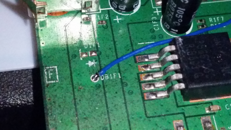
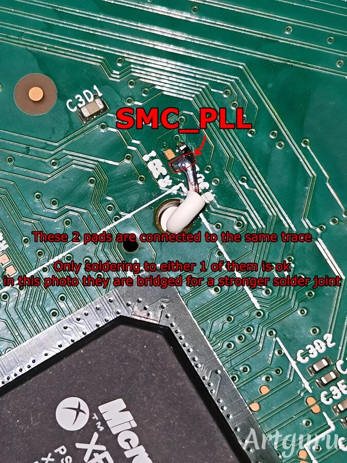
- Alternative SMC_PLL (Top)
Xbox 360 S (Trinity)
On Trinity, it is highly recommended to use a 5K Ohm resistor on the PLL wire. The diode/resistor on the POST wire is not used on Trinity.
When using a through hole resistor for PLL, it is recommended to solder it in the middle of the wire instead of soldering it directly to a pad or via. The wires will be less stiff than the diode's legs, causing less strain to the joint if it moves around.
Make sure the PLL wire is not nearby any high noise areas, like inductor coils.
Diagram
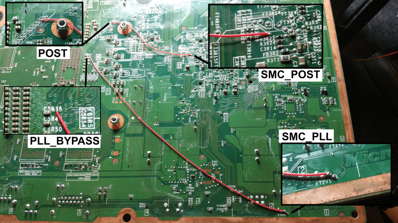
Close-Up Solder Points
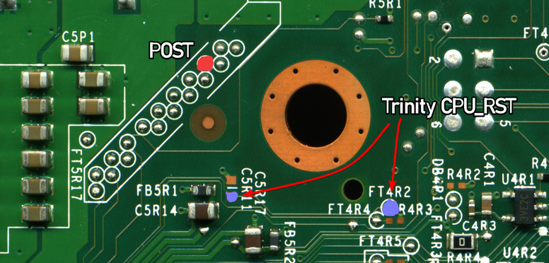
CPU Points
- PLL_BYPASS (Bottom, no alt point!)
- CPU POST (Bottom, RST can be ignored with RGH 3)
SMC Points
- DBG_LED (used for SMC_PLL)
- Bottom (FT2V1)
- Alternate Top Points
- DB2G3
- R3D2
- DB2G3
- Bottom (FT2V1)
- GPU_RST_DONE (used for SMC_POST)
- Bottom
-
- Bottom
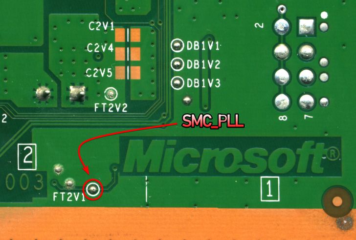
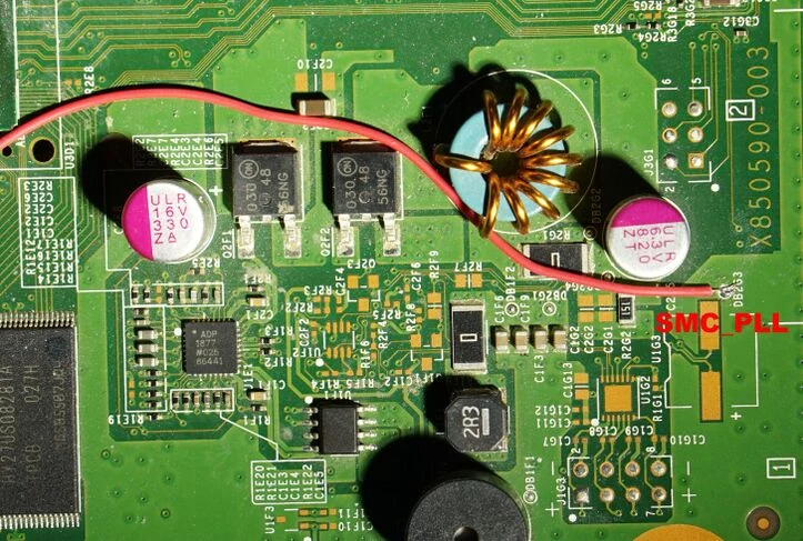

Xbox 360 S/E (Corona/Waitsburg/Stingray)
The 1K Ohm resistor on Corona motherboards is optional, as the GPIO and the CPU's PLL_BYPASS both operate at 1.8v, but still recommended. The resistor/diode on the POST wire is also not used on Corona.
When using a through hole resistor for PLL, it is recommended to solder it in the middle of the wire instead of soldering it directly to a pad or via. The wires will be less stiff than the diode's legs, causing less strain to the joint if it moves around.
Make sure the PLL wire is not nearby any high noise areas, like inductor coils. The connection points for Corona are quite close to each other, so this may not be as much of a concern compared to the older boards, but still worth noting.
Make sure to check if the POST point on the bottom is enabled or not using the diagram near the beginning of this page.
Diagram
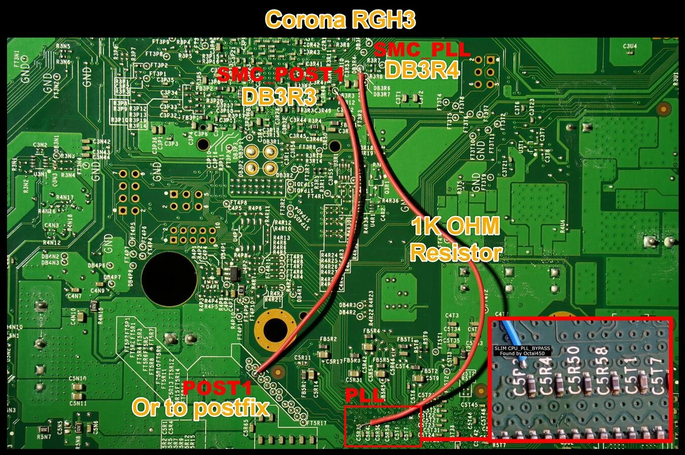
Close-up Solder Points
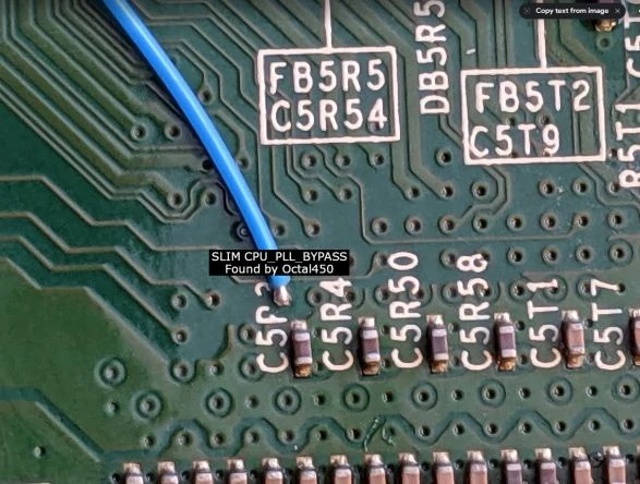
- CPU PLL (Bottom, no alt point!)
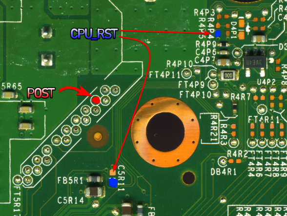
- CPU POST (Bottom, RST can be ignored with RGH 3)
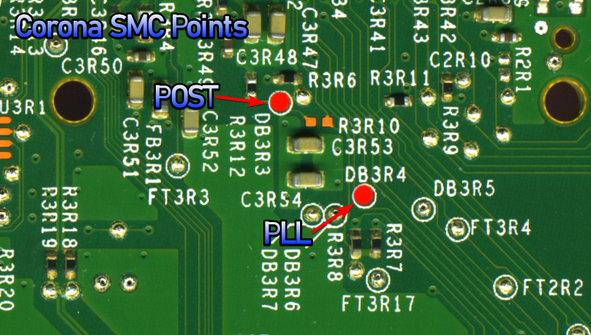
- SMC POST and PLL (Bottom)
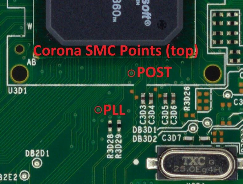
- Alternate SMC POST and PLL (Top, Requires scraping)
Testing the Console
Once you've finished soldering, clean up any flux with isopropyl alcohol and cotton swabs. Partially re-assemble your Xbox 360, ensuring that:
- Heatsinks are attached, if they were removed for some reason
- Fans are in place and plugged in. On a phat console, the fans can be angled on top of the heatsinks to cool them for testing
- The RF board is plugged into the front of the console
- An A/V or HDMI cable is plugged into the Xbox 360 and into a TV or monitor
- A power brick is plugged in to both the wall and Xbox 360
- (Optional) An Ethernet cable is plugged into the Xbox 360 and a LAN (e.g. a switch, router, or directly to a PC)
Turn on your console, and it should boot into XeLL RELOADED within a minute. If you don't have an Ethernet cable connected, write down (and/or take a picture of) the "CPU Key" listed on screen. If the console doesn't boot into XeLL, check all previous steps and double check your wiring accuracy and quality.
If you used Bad Update to dump/flash your console's NAND with the Updating your Firmware guide, the steps of getting the CPU key can creating a new NAND were already completed from that process, in which case your console will just boot into the modified Freeboot operating system, thus you can jump to the Cleaning Up section.
Console powers off immediately on startup
This is a common issue mostly affecting phat consoles but can also happen on slims.
The hacked SMC program running the RGH 3 exploit can get stuck waiting for the right POST signal. As a failsafe, a watchdog timer inside the SMC will reset the console to standby mode if the SMC program hangs.
Causes of this can include:
- POST wire is not connected to the right POST pad
- Excessive noise on the POST wire
- If a diode is being used, it's been wired in reverse or isn't switching fast enough
- You might have a super uncooperative Jasper (more details here)
If you are reverting your console to retail or converting it to RGH1.2, you must flash a different SMC program. You can't simply remove the wires and move on, as the RGH 3 program will get stuck waiting for a POST that never arrives.
You cannot run a retail NAND with the RGH 3 POST wire in place if you have a Falcon/Jasper/Tonasket/Trinity motherboard. The SMC POST pin is shared with a GPU signal (GPU_RESET_DONE) because there aren't enough free I/Os on the SMC. On RGH 3 the SMC is hacked to ignore this, but a retail (or other RGH SMC) isn't and conflicts between the GPU and POST buses will result in the same problem. On Coronas, RGH 3 uses a free I/O line and therefore isn't subject to this issue.
Writing a New NAND Image
Once you have successfully booted XeLL, we can use XeBuild to make a Freeboot image with your now obtained CPU key, which is a modified version of the OS built specifically for your console.
You may've already selected the corresponding options if XeLL was flashed earlier with a NAND flashing tool, but the instructions and settings are still covered here just in case.
Note regarding non-Corona with RGH 3 wiring and retail NAND
Falcon, Jasper, Tonasket, & Trinity consoles with the RGH 3 exploit and unmodified retail NAND are incompatible, as the GPIO used for the POST wire is the one used by GPU_RST_N, a signal responsible for one of the RROD codes.
You can use modified freeboot NAND (as already instructed by the guide below), or wire in a switch to disconnect the POST wire for RGH 3.
For these consoles, you also have the option to apply the following patch with J-Runner with Extras. Follow the directions in the included readme.txt file.
Decrypting & Patching the NAND
- Go to J-Runner and select
...next to the Load Source field and select one of your original NAND dumps if not already selected. In the upper right of J-Runner, ensure theGlitch2radio button is selected. If RGH 3 XeLL (which is the .ecc file) was written to the NAND earlier,Glitch2andRGH3should already be enabled. If not, or you used Bad Update to do a NAND dump, enable them.- If you have an Xbox 360 E Stingray motherboard, you may also need to enable
WB 2K. Many Stingray motherboards use Winbond W641GG2KB-14 RAM, which is incompatible with the older Corona bootloader used by default. This setting just installs a newer bootloader that's compatible with this RAM type, which was already installed on Corona/Waitsburg through system updates. This means that it can still be enabled on Xbox 360 S Corona/Waitsburg motherboards, or Stingray boards with Samsung RAM, though it won't gain any benefits. You can leave this setting disabled if you know your board has Samsung RAM, but if you forgot or are unsure, then just enable the option to be safe.
- If you have an Xbox 360 E Stingray motherboard, you may also need to enable
- Enter your CPU key into the CPU Key text field.
- The J-Runner software itself can automatically grab the CPU key of a console if both are connected to the same network. To do this, enter the IP address XeLL gives you into the lower right of the app. You can then click
Get CPU Keyand XeLL will automatically decrypt the retail NAND dump you backed up earlier. It is recommended to also click "Extract Files" in order to extract additional data from the NAND, such as your keyvault. - You can also use XeLL's built-in web server to get the CPU key; simply enter the Xbox's IP address in your preferred web browser. You will see information about the console, and the CPU key can be easily copy and pasted from this web page. It is recommended to download the keyvault as well.
- If you didn't have access to an Ethernet cable to plug the Xbox into a PC or LAN, you can manually type the CPU key into J-Runner in order to decrypt your original NAND dump.
- The J-Runner software itself can automatically grab the CPU key of a console if both are connected to the same network. To do this, enter the IP address XeLL gives you into the lower right of the app. You can then click
- Go in the
Patchestab and enable any desired options. Commonly used ones will be listed below.noinitmuwill disable the ability for the console to initialize the internal memory unit's usable storage during the boot process. This is extremely useful for Corona/Waitsburg/Stingray consoles that came with 4 GB NANDs, as it prevents any accidental writes to the eMMC by a significant amount.- This patch also applies to big block 256/512 MB NANDs that can be used on Jaspers, Tonaskets, and Trinities, but since the big block NANDs tend to have perfectly fine reliability, using this option is more of a preference (like if the desired console only has one storage device connected (such as an internal HDD), and you want to avoid having to deal with storage device selection pop-ups in games)
- Noinitmu is not supported with retail NAND images; only Glitch/Glitch2/Glitch2m Freeboot images.
Key Fixaddresses minor issue with how Corona Glitch2 images are made by XeBuild, where a second copy of one of the CPU's secret keys isn't actually created with the Freeboot patches. While it doesn't normally cause an issue in the majority of games, this patch will fix the infinite loading bug that can occur on RGH Corona/Waitsburg/Stingray motherboards in rhythm games developed by Harmonix or Neversoft, like the Rock Band, Guitar Hero, or Dance Central series of games, as they actually read from the second copy of this key.UsbDSecwill remove the console's security restrictions of XInput peripherals, allowing you to use various controllers or controller adapters as long as they output the XInput protocol. This is also mentioned in the Using Modern Controllers page.XL HDDandXL USBenable the ability to use USB/SATA storage larger than 2 TB, with the caveat that they have to be formatted in a special way with FATXplorer.- Note that XL patches will also disable the ability to use non-XL formatted storage! This is explained further on the FATXplorer website.
- If you have a Falcon or Jasper/Tonasket model, choose a MHz option in the dropdown menu. 27 MHz is the default.
- J-Runner with Extras version 3.4.0 and later includes an overclocked (OC) ECC option in the MHz dropdown to improve boot consistency. It is recommended to use a 470 ohm resistor on the POST line. While it may not be optimal, the OC files will still work with an older RGH3 diode install.
- Note for Falcon: The 27 MHz and 10 MHz falcon ECCs use a Jasper SMC program, while the OC ECC uses a Falcon SMC program. Flashing a NAND image containing a Falcon SMC on top of an image that contains a Jasper SMC might result in an 0021 RROD, if this occurs simply unplug the console for a hard reset of the SMC.
- Click "Create XeBuild Image". This will take a few moments, and when it is finished, it will be a
updflash.binfile in J-Runner's working directory. You can click theShow Working Folderbutton in order to quickly get to it.
NAND Flasher Method
- Power down the console and connect your programmer to the motherboard.
- If you are using an xFlasher, ensure the switch is set to
SPI.
- If you are using an xFlasher, ensure the switch is set to
- In J-Runner, select the
updflash.binXeBuild image created by the program and click "Write NAND". - Disconnect your NAND programmer from the console's motherboard and the PC when the process completes.
- Check if the console boots to the Microsoft dashboard. If it successfully boots to the dashboard, it is an indication that you've successfully hacked your console.
- Continue in the Cleaning Up section.
XeLL Method
- Copy the
updflash.binfile created by J-Runner to the root of a FAT32 formatted USB storage device and plug it into your powered-off console. - Turn on your console. It will boot into XeLL and begin flashing your NAND. Once it has finished, it will power off your console.
- With Bad Update, you can also access XeLL with either XeUnshackle directly, or the XellLaunch application.
- Turn it back on, and it should boot to the Microsoft dashboard, which is an indication that you've successfully hacked your console.
- Continue in the Cleaning Up section.
Cleaning Up
- Boot the console several times and ensure it boots consistently. If not, make sure your wiring is clean and neat and avoids noisy areas, like any inductor coils. Run the wires near the X-Clamps for best results.
- If you are on a Falcon/Jasper/Tonasket console and have issues with booting, you can configure the RGH 3 clock speed in J-Runner from 10 MHz to 27 MHz or vice versa. J-Runner with Extras version 3.4.0 and later includes an overclocked ECC option in the MHz dropdown to improve boot consistency.
- Remove the NAND programmer wires from the console and clean the points. Clean all flux off the board, allow it to dry, and test it once more before re-assembling.
- You may want to leave your Xbox 360 disassembled so that you can disable the eFuse-blowing circuit so you can't accidentally install official updates on your console.
Installing XeXMenu
- Plug a flash drive into your Xbox 360 and navigate to Console Settings > Storage. Select the flash drive and format it.
- Make sure you have hidden folders enabled on your PC.
- Go into
File ExplorerunderViewon top, check markHidden Items.
- Go into
- Plug the flash drive into your PC. Open the
Contentfolder, select "New Folder", and name it0000000000000000(16 zeroes). Open the new folder, make another folder under the nameC0DE9999, open that folder, and finally make one last folder called00080000The full folder path should now be0000000000000000/C0DE9999/00080000/. - Extract the
C0DE99990F586558file from the XeXMenu archive to the0000000000000000/C0DE9999/00080000/directory on the USB drive. - Safely eject your flash drive and plug it into your Xbox 360. Navigate to the Demos section of your dashboard, and it should list XeXMenu there. Select it to launch it.
- You can install XeXMenu to your hard drive by going to Console Settings > Storage and copying it from your flash drive to the hard drive.
From here, you can install any homebrew or mods that you want. See this page for a list of recommended modifications and applications to install.