This guide will walk you through obtaining NAND dumps, creating a .bin/.ecc file for XeLL, and writing it to the console using a dedicated NAND flasher.
This guide applies to all motherboards, except 4GB Corona motherboards. You can read the guide for 4GB Corona NANDs here.
If you instead want to use an LPT cable for NAND dumping, you can view the corresponding guide here.
Equipment Needed
- One of the following NAND programmers:
- xFlasher 360 by Element18592
- Raspberry Pi Pico (or other RP2040 based SBC) flashed with PicoFlasher
- JR Programmer
- NAND-X
- Matrix Flasher
- One of the following USB cable types to connect the NAND programmer to a computer:
- Mini-USB if you are using a NAND-X, Matrix, JR Programmer, or older xFlasher 360
- Micro-USB if a Raspberry Pi (or another RP2040 SBC with a micro USB port) for PicoFlasher
- USB-C cable if using a newer xFlasher 360 or USB-C RP2040 SBC with PicoFlasher
- A soldering iron, solder, flux, and isopropyl alcohol with cotton swabs
- If using a Matrix or Raspberry Pi Pico, 28AWG or 30AWG wire (Solid core recommended)
NAND Flasher Comparison
There are a few different tools for reading your NAND chip: xFlasher 360, Nand-X, JR Programmer, Matrix USB NAND Flasher, PicoFlasher, or a LPT cable. Consider the pros and cons below and choose the method that’s right for you. An LPT cable is not recommended as it's extremely slow, requires more work than other options, and cannot be used to program glitch chips.
A guide on how to dump and write to a standard NAND can be found here.
| Device | Pros | Cons |
|---|---|---|
| xFlasher 360 |
|
|
| PicoFlasher |
|
|
| 4GB USB Tool |
|
|
| SD Card Tool (any brand) |
|
|
| Nand-X |
|
|
| Matrix USB NAND Flasher |
|
|
| LPT Cable |
|
|
Installing Drivers
- Download and extract J-Runner with Extras.
- Press Win+R and type
devmgmt.mscand press Enter to open Device Manager. You can also get to it by searching for it in the Start menu. Plug the USB cable into both your programmer and your PC. Windows should find it and it will appear asJ-R PROGRAMMERorNAND-Xor twoUSB Serial Portentries under the "Other Devices" category in Device Manager. - Install drivers:
- (xFlasher): Launch J-Runner with Extras, plug in your xFlasher, and click the xFlasher menu and "Install Drivers".
- (JR Programmer / NAND-X / Matrix): If you are on Windows 10, you will need to disable signed driver enforcement. Once done, right-click the programmer’s name in Device Manager and select Update Driver Software… > Browse my computer for driver software > Browse… > navigate to your J-Runner folder > common > drivers > OK > Next. You may receive a popup saying that Windows can’t verify the publisher of the driver, select the option to install it anyway. It should successfully install and file your device under its own category in Device Manager. Your programmer’s LED light should also turn green.
Soldering to the Motherboard
xFlasher / JR Programmer / NAND-X
Your kit will come with a cable with a white plug on one end and open wires on the other. Solder each wire according to the diagram below. Note that the wire colors may be different than the picture below in a knockoff kit, so go off of the wire position and not the color of the wires in that case. 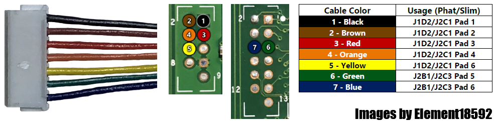
Once you’ve finished soldering, clean up any flux with isopropyl alcohol and cotton swabs.
Matrix
Solder a wire to each of the labelled pads on the Matrix and to the corresponding pads marked J1D2/J2B1 (phat) or J2C1/J2C2 (slim) on the motherboard in the diagram below.
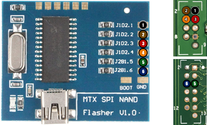
Once you’ve finished soldering, clean up any flux with isopropyl alcohol and cotton swabs.
PicoFlasher
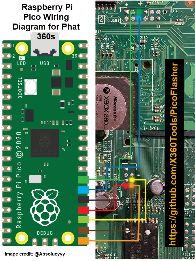
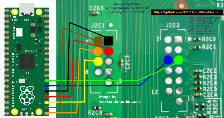
Solder each wire (or connect a pin header wire) to each of the labeled pads on the Raspberry Pi pictured in one of the diagrams below and then solder the other ends of the wires to each of the corresponding pads on the motherboard.
Once you’ve finished soldering, clean up any flux with isopropyl alcohol and cotton swabs.
Original & hax360's Firmware
Pinout
NAND
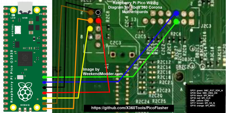
| GP16 | SPI_MISO |
| GP17 | SPI_SS_N |
| GP18 | SPI_CLK |
| GP19 | SPI_MOSI |
| GP20 | SMC_DBG_EN |
| GP21 | SMC_RST_XDK_N |
| GND | GND |
eMMC
| GP6 | FLSH_DATA<0> | U1D1 pin 16 |
| GP7 | FLSH_WP_N (CMD) | U1D1 pin 3 |
| GP8 | FLSH_CE_N (CLK) | U1D1 pin 2 |
| GP9 | MMC_RST_N | U1D1 pin 1 |
| GP21 | SMC_RST_XDK_N | Same as 16MB flash |
| GND | GND | U1D1 PIN 4 |
Phat Diagram
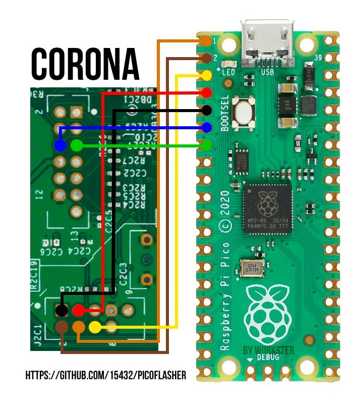
Note that 15432's firmware uses the GP0 though GP5 pins instead of the ones on the diagram. You can match them up with the pinout table shown below.
Trinity Diagram
Note that 15432's firmware uses the GP0 though GP5 pins instead of the ones on the diagram. You can match them up with the pinout table shown below.
Corona 16 MB Diagram
Note that 15432's firmware uses the GP0 though GP5 pins instead of the ones on the diagram. You can instead use the alternate diagram below this one if you're using his firmware.
15432's Firmware
Pinout
| GP0 | SPI_MISO |
| GP1 | SPI_SS_N |
| GP2 | SPI_CLK |
| GP3 | SPI_MOSI |
| GP4 | SMC_DBG_EN |
| GP5 | SMC_RST_XDK_N |
| GND | GND |
Corona Diagram
When using the PicoFlasher fork by 15432, you use the console's SMC programming header regardless of if the console has 4 GB or 16 MB flash memory.
Reading the NAND
- Plug your Xbox 360 power supply in, but do not turn the console on. You can leave the RF board disconnected to prevent turning it on by accident.
- If you are using an xFlasher, set the switch to
SPI.
- If you are using an xFlasher, set the switch to
- Plug the white end of the cable into the bottom port of the programmer. Plug the USB cable into the programmer and your PC.
- Launch J-Runner. Select "Read NAND" in the top left. It may prompt you for your Xbox 360’s model, make the correct selection and click OK. If everything is wired properly, it will read your NAND twice and automatically compare the dumps. If it says "Device Not Found" or anything about missing CB/CD files, see the troubleshooting steps at the bottom of this page. If you get messages about bad blocks, ignore them. When it has finished, it will tell you if the two dumps are an exact match. If they are, you can close J-Runner and proceed. If they aren’t, take more dumps until you get matching ones.
- Copy both of the dumps to a safe place such as cloud storage or send it to yourself in an email to keep them safe. They are located in the
outputfolder in the J-Runner directory.
(Phat Only) Checking your CB if it's JTAGable
This section is only if you have a phat Xbox 360 that has a dashboard/kernel version of 2.0.7371.0 or lower.
Open J-Runner and select "…" next to the Load Source field and choose the nanddump1.bin or nanddump2.bin file. On the right-hand side, note the value next to the 2BL [CB] label. If your CB is on the list below, your console is JTAGable. Any newer CB which is not on the list will be patched.
| Model | Exploitable CB Versions |
|---|---|
| Xenon | 1888, 1897, 1902, 1903, 1920, 1921 |
| Elpis | 8192 |
| Zephyr | 4540, 4558, 4570, 4580 |
| Falcon/Opus | 5760, 5761, 5766, 5770 |
| Jasper | 6712 & 6723 |
| Tonasket | none |
Writing XeLL to the NAND
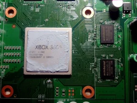
- In J-Runner, select "…" next to the Load Source field and choose your
nanddump1.binornanddump2.bin. - Select the appropriate radio button in the top right of the window:
JTAG- For JTAG, R-JTAG, or R-JTOP.Glitch- For RGH1.Glitch2- For RGH1.2, RGH2, RGH3, EXT_CLK, Muffin/Mufas, or S-RGH.Glitch2m- Same as Glitch2 but only used if your eFuses are in a non-bootable state. Rather than using the real eFuses from the console's CPU, it uses virtual eFuses stored on the NAND instead.
- Put a check in the appropriate checkbox (if applicable) in the top right of the window:
- If you are using JTAG, select
JTAGand leave the R-JTAG checkbox disabled.- If you are using R-JTAG or R-JTOP, the
R-JTAGcheckbox would be enabled. - If you are not on a Xenon console, enable
Aud_Clampfor either of these three modifications.
- If you are using R-JTAG or R-JTOP, the
- If you are using RGH1.2, S-RGH, EXT_CLK, or Project Mufas, enable
SMC+ - If you are using RGH2 or RGH2+, enable
CR4- If you are using RGH2 with an X360ACE on Zephyr/Falcon, enable
SMC+instead.
- If you are using RGH2 with an X360ACE on Zephyr/Falcon, enable
- If you are using RGH3, select
RGH3 - If you have an Xbox 360 E Stingray motherboard, enable
WB 2K- Some Stingray motherboards use Winbond W641GG2KB-14 RAM, which is incompatible with older Corona bootloaders. This setting just installs a newer bootloader that's compatible with this RAM type, which was already installed on Corona/Waitsburg through system updates. This means that it can also still be enabled on Xbox 360 S Corona/Waitsburg motherboards, or Stingray boards with Samsung RAM, though it won't gain any benefits. You can leave this setting disabled if you know your board has Samsung RAM, but if you forgot or are unsure, then just enable the option to be safe.
- If you have an Elpis motherboard, enable
Elpis- Many Elpis motherboards have Samsung RAM, which is incompatible with the Falcon bootloader that's used by default with Xenon Glitch2 images. This setting just installs an Elpis bootloader that's compatible with this RAM and GPU configuration, which was already installed on refurbished/remanufactured Elpis motherboards from the factory. This means it can still be used on Elpises with Infineon/Qimonda RAM, though it won't gain any benefits. You can leave this setting disabled if you know your board has Infineon/Qimonda RAM, but if you forgot or are unsure, then just enable the option to be safe.
- If you are using JTAG, select
- Select the
Create XeLLbutton and wait for it to finish. - Select the
Write XeLLbutton, select your system, and press OK. It will write the XeLL to the first 50 blocks of the motherboard's NAND.- If it says "Device Not Found" or Flash Config 0x00000000, see the troubleshooting steps at the bottom of this page.
- Once it has successfully written to the motherboard, unplug the power cable from your Xbox 360 and unplug the USB cable from the computer and programmer.
- Go back to the page you were originally on for wiring instructions.
Troubleshooting
- "Device Not Found"
- Re-insert the USB cable
- Check that the drivers are properly installed
- "Flash Config 0x00000000"
- Check that your power brick is plugged in, with an amber colored LED, and that it is plugged into your console completely (console turned off).
- Check your soldering to your motherboard. Each point should be solidly connected and have a shiny round joint.
- Check that you’ve cleaned up any flux you had used. Depending on the type, it may be conductive and cause issues. MG 835 is strongly suggested to avoid this.
- "Wrong Version"
- Re-insert the USB cable
- What should I do if I ripped off a soldering pad?
- Look online for an alternate point to solder onto. Practice more on junk electronics before attempting to continue.